Type "G" Signal
I was lucky for having chosen the Reading because, for reasons unknown, I've always had a preference for Type "G" or "Tri-Light" signals—as did the Reading, by happy coincidence. I hadn't decided whether or not I'd attempt to build a Z scale signal for the layout, but after having struggled through the construction of the crossing flasher, the signal seemed like a no-brainer by comparison. But since my layout has a single-track main, a double-headed signal seemed be the most appropriate type to use; this upped the construction challenge just a bit, but I was still gung-ho; after all, making something once may be hard, but making it again is usually easy.
While doing my research, I found Railroad Signals of the US was useful, especially as it provided an example of a double-headed Type "G", as well as technical drawings with dimensions. When it came time to start construction, I immediately arrived at the same sticking point as I had with the crossing flasher: the targets. In a flash of inspiration, I took an ordinary paper punch to a scrap of .005-inch sheet brass. Voilà! The result was a surprisingly clean, flat disk. It seemed almost too easy...
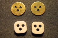
Next, lamp housings were cut from plain .030-inch sheet styrene. After rounding their corners, one of the two was marked for drilling; the holes were arranged such that the anodes of all three LEDs would align across the middle, allowing them to be soldered together to simplify wiring. The brass targets were bonded together with CA and then bonded to a scrap of PC board; the two styrene housings were tacked to the targets with white glue. This sandwich helped to keep all of the parts aligned, as well as make for clean holes in the targets (drilling thin sheet brass by itself is asking for trouble). After drilling the three holes with a #62 bit, the housings were popped off the targets, and the targets were sliced away from the PC board and soaked in acetone to separate and clean them. The housings were then re-drilled with a #55 bit to accommodate the LEDs.
Hoods were made from .060-in. OD thin-walled brass tubing just as they had been for the crossing flasher. These were bonded to the targets with CA. After priming and painting the targets black, I applied red, yellow and green Tamiya clear paint to the openings with the point of a toothpick. While this was drying, I installed the LEDs in the lamp housings, which press-fit in the holes from the back. Then I wired the LEDs with #40 solenoid wire, and gently twisted the wires together to simulate the conduit that runs from the bottom of the signal to the stanchion. After securing the LEDs and the wiring with CA, I bonded the housings to the targets.
Two brackets for the signals were fashioned from pieces of .045-inch brass square stock. One end of each was shaped to fit against .035-inch OD thin-walled brass tube by grinding a detent with a diamond cutting wheel in a Dremel tool; the other end was ground to a flattened taper and drilled to pass the LED wires. Both brackets were soldered to the stanchion at once. Then I added ladder parts from the TrainCat #0300901 Type "D" Mast Signals kit, which by happy coincidence exactly fit the tubing I used for the stanchion. After bonding the ladder and platform to the stanchion with CA, I sprayed the assembly with dull silver.
Finally, the signal heads were installed: the wires were threaded through the holes in the brackets, and then down the stanchion. Without a doubt, this was the most challenging—and most the tedious—process of the project. The first few wires went down fairly easily; but as the stanchion became ever more crowded with wires, each new one became much less cooperative. I was literally teasing the wires into the tube with a tweezers, one millimeter at a time, and if a wire became stuck, it would get kinked, and I'd have to pull it out, straighten it, and start over. Yet, I could not come up with any other means of doing this, so I just had to grin and bear it. The only way I could describe it is something like trying to stuff cat hairs up the sharp end of a hypodermic needle. Finally, when the last wire was through, I secured the signals to the brackets with CA, and painted the wire bundles between the brackets and the stanchion with thick grey paint to represent the flexible wire conduits on the real thing.
With that bit of nastiness out of the way, the rest was all downhill. I made a footing for the signal stanchion from the next size up brass tubing, followed by a bit of styrene tubing. Then I made a footing from thick sheet styrene, cut to a rectangle and laminated to add thickness. After drilling a hole for the signal's styrene tube footing, I bonded the signal in place on the base, and added a tiny rectangle of strip styrene as a footing for the ladder. Finally I bonded a stack of PC board railroad ties around three sides of the base.
The last step before installing it on the layout was to touch up the paint, then lightly weather the signal parts—I was not after a neglected, ancient look as I am so often for other things. I also painted the railroad ties with tie brown, followed by driftwood stain and finished off with an India ink wash.
Installing the signal on the layout was a bit of a chore. The spot where it was to go wasn't designed for it, so I had to tear up some finished scenery and hack a hole through the subsurface support. Since the area was mostly glue, things I removed tended to bring along more than desired, so the hole wound up about twice the size needed. I also had to carve a substantial hole in an access panel support right under the station to provide access for the wiring.
After gluing the signal base to the exposed edge of the track subroadbed, I filled in the holes with a variety of materials, including caulk, bits Foamcore, and ground foam. This process was complicated by the fact that everything was right up against the coal trestle, so the area in which I had to work was extremely limited—it all felt a bit like brain surgery. Naturally, accidents happened, and now I must repair the handrail on the coal trestle, the signal relay box, and the ballast along the edge of the station platform.
I made a terminal board for the signal's eight solenoid wires by carving the surface of a scrap of PC board into squares. After soldering the signal wires to the homemade pads, I attached the PC board to the layout with double-stick foam tape. The signal aspect is controlled manually with toggle switches.
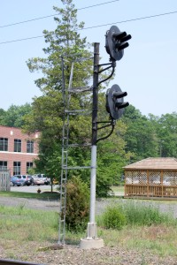
This example stands beside (former) Reading tracks in West Trenton, NJ.
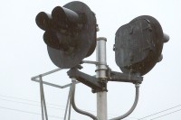
This double-headed version was found in Lancaster, NY. Photo: Todd Sestero.
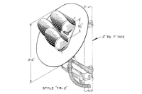
Here's a drawing of a US&S Style TR-2 signal head, from Todd Sestero's site.
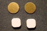
Here are the paper-punch targets, with the styrene lamp housings.
All of the parts are sandwiched together for drilling, then separated.
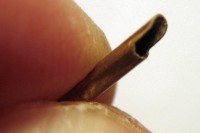
A hood starts with a shape ground into the end of thin-walled brass tube.
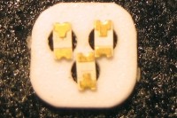
The LEDs are installed in the lamp housing part from the back.
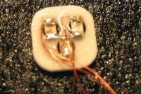
The LEDs are wired with fine solenoid wire and bonded in place with CA.
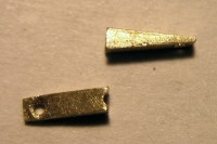
Brackets that attach the signals to the stanchion are made from solid brass.
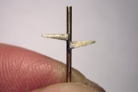
The brackets are soldered to the stanchion for strength.
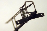
The ladder and platform are assembled to the stanchion, and then painted.
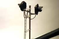
The signal heads are mounted on the brackets, and the wires are threaded.
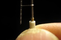
A footing is fabricated from telescoping brass tube followed by styrene tube.
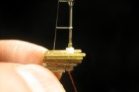
A base is built from thick sheet styrene covered with railroad ties.
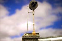
The finished signal is weathered and ready for installation.
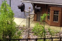
The signal is installed across from the passenger station.
Copyright © 2007-2013 by David K. Smith. All Rights Reserved.
Images from Todd Sestero used by permission.
