![]()
Signal Relay Box
Before I get into the nitty-gritty of this ubiquitous little detail, I thought I'd pass along some helpful hints on how to best make use of such items. While it may appear to the casual observer that relay boxes are scattered around railroads at seemingly random locations, there really is a purpose behind their placement. The boxes house relays and other electrical paraphernalia required for signals, crossing flashers and related equipment. As a consequence, you'll most often find them near signals, switch towers, and grade crossings. Some of these boxes will have access doors on both sides.
The BLMA relay box I added for the signal is a nicely-made little etched brass detail item. As it comes, however, it's not a "complete" model. With no intent to disparage BLMA, nearly all relay sheds sit on some kind of footing or set of legs. Some of the more interesting installations have built-in platforms on which railroad personnel stand when accessing the equipment (an example is shown above right). I decided to model this variety so as to enhance the appearance of the box, particularly since it's located very close to the front edge of the layout.
After cutting the box out of the fret and folding it up, I secured the joints with solder. For a tiny model like this, soldering just takes a few seconds and makes it very sturdy. But I thought the assembled box looked a little plain, so I used part of the fret to make a new roof, which I attached with CA such that it overhung the doors slightly. The bottom of the box was plugged with a scrap of styrene.
The footing was cut form a scrap of sheet styrene, but only after installing the legs, as it was easier to drill the holes in a larger part. The legs were a product of thinking outside the Z scale parts box: they were cut from a set of N scale Gold Medal Models industrial railings. The wiring conduits were bits of styrene rod. The assembly was sprayed with Testors Light Aircraft Gray, and the legs and conduits were brush-painted with dark grey paint.
After bonding the relay box to its legs, I simply dipped the assembly in Rustall a couple of times, allowing it to dry between each dip, and then dabbed on various other rust-colored washes. The stripwood step was added last, and aged with India ink wash.
A bit of scenery had to be carved out to accept the footing; once the relay box was in place, I surrounded it with weeds. It may seem like a lot of work for a miniscule detail, but the cumulative effect of many such details is immeasurable.
NOTE: On 22 April 2009 this box was moved to a new location across from the station to support the signal instead of the crossing flasher on Canal Street. The Crossing flasher has its own relay box, complete with battery box.
Here's the stock Z scale relay box as BLMA sells it.

This is a fairly typical real-life relay box installation.

These boxed illustrate the variations in weathering they can acquire.

The relay box is folded and soldered together.

The etched brass "legs" are installed in holes drilled in sheet styrene.

The footing is trimmed to size and details added before painting.

A hole is cut into the scenery to accept the footing.

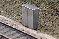
The finished relay box is now a tiny focal point of detail.
![]()
![]()
Copyright © 2007-2013 by
David K. Smith. All Rights Reserved.
BLMA product photo used with permission.