![]()
Crossing Flasher, Part 1 of 2: Stanchion
Canal Street needed crossing flashers. But for a while I thought that I'd shot myself in the foot: in my rush to build and install the crossing shanty, I'd left no room for a crossing flasher. When it finally dawned on me that I'd screwed up, I was convinced that it would be too much trouble to move the footing, which left the crossing flasher project in limbo.
Months passed, and eventually I came to realize that it wasn't going to be such an onerous task to move the shanty after all—and indeed it was finished in a matter of minutes. The worst aspect of the task was working so close to the coal trestle switch ground throw and the crossing relay box, which are tiny, delicate, non-removable details. It was simply a matter of very carefully slicing the scenery around the shanty footing, extracting the chunk of freed scenery, creating a new support for the footing, and re-installing it.
With that bit of ugliness out of the way, I was at last able to start modeling. I'd already researched cantilever-style flashers, and had a good idea how I was going to build it. Meanwhile, I began searching for a circuit that would make the flashers behave like "old fashioned" tungsten lamps instead of LEDs, the distinction being that tungsten lamps brighten and dim perceptibly, while LEDs flash on and off instantaneously. I soon found the perfect candidate: Ngineering flasher circuit #N8038. There was just one small problem with this product: it would only support two pairs of LEDs, whereas I'll have four pairs, because I'd have flashers facing both directions, as they are in life, for two flashers—the cantilever, plus its partner on the other side of the tracks—and all of these lights would need to be synchronized.
Fortunately, Ngineering's proprietor, Tim Anderson, is very responsive to inquiries, and he indicated there was a solution to my problem, although the product I'd need—an expansion board—was still in development and not due to be released for another month or two. This was not a big deal; I'm not going anywhere, and it would not stop me from proceeding with the construction of the flashers since Tim was kind enough to provide a description of the wiring scheme I'd need to employ for the LEDs.
I could then turn my attention to other problems, such as making the flasher removable from the layout. Long ago I learned—the hard way—that tall, delicate objects close to tracks are always at risk of damage, so with very rare exceptions, I make such things removable—the crossing shanty is a prime example.
My first port of call was the "junk drawer" where I store the remains of old gutted VCRs and suchlike. There I found some nice small connectors with wires, and given that one of the connectors perfectly fit the hole left after moving the crossing shanty footing, it seemed to be the right starting point. It was then a matter of fabricating a matching plug. I began with a small scrap of PC board; after scribing the copper to make electrically-separated pads, I drilled #76 holes and soldered .020-in. brass wire pins in place.
Thus I had a plug that also made a sturdy base for the flasher pole. I soldered a length of .035-in. thin-walled brass tubing in a #65 hole drilled in the PC board, then trimmed the PC board down to its final size. Using the pole for alignment, I bonded the connector directly to the exposed track subroadbed in the hole with five-minute epoxy. (The PC board plug was wrapped with masking tape to prevent it from being bonded to the layout along with the connector.) This was followed by scenery filler material—my "patented mix" of gray caulk and fine ballast, which is what I'd used for the road shoulder, so it blended in perfectly.
Once the connector was fully set, I pried the plug out, cleaned it up, and got to work on the flasher. I started by making a footing from a piece of .080-in. square strip styrene drilled endwise to fit over the pole. After sanding it to shape and bonding it to the plug, the footing was capped with a short piece of the next size (.050-in.) of brass tubing. Then came the main cantilever arms, which were made from .020-in. brass wire soldered to the pole on rings made of tiny segments of .050-in. tubing; the diagonal braces at the top were made from .010-in. brass wire.
This quickly brought me to the point of having to make the flasher lights, and with the arrival of my order for TrainCat Type "D" Mast Signals (#0300901), it looked as if I'd found a way to make the flasher targets at long last. The kit also yielded a source for the catwalk, which I made from three pieces of signal platform grafted together. The ladder, which came from a Micron Art Z Scratch kit #91401, completed the main flasher assembly.
Except for height, all dimensions were made by eye based on reference photos and drawings. Now comes the confession: it's about four feet too short. I deliberately made it shorter than it should be because of its uncomfortable proximity to the crossing shanty—if I'd made it the proper height, it would very nearly touch the shanty roof. But since I'm thinking about leaving the shanty off the layout, it was an unfortunate decision; still, I don't think anyone would notice that it was too short unless I put a tractor-trailer under it, so I'm not concerned enough to rebuild it. Also, the Type "D" targets are 30 inches in diameter, whereas standard crossing signal targets are 24 inches, but I'm not losing any sleep over that, either.
Anyway, having solved the long-standing dilemma of what to use for targets, it was time to delve into the world of SMD LEDs and other absurdly tiny objects.

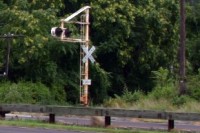
This crossing flasher in Lakewood, NJ is an example of the general type I need.
Found on the Internet, this crossing flasher has the right proportions.

This drawing from a DOT website is also a useful reference.

First, the crossing shanty must be shifted away from the track.

The scenery surrounding the footing is sliced with a knife.

The footing is carefully pried out of the scenery.

The opening is cleared out and a new Foamcore support is installed.

The footing is cleaned up and glued to the Foamcore support.

This junk box connector fit in the space left after moving the crossing shanty.

A plug is made from a scrap of PC board and brass wire for pins.

The connector is installed in the layout using five-minute epoxy.

Scenery material is filled in around the connector and the shanty footing.

The cantilever signal is complete and ready for the flashers themselves.
![]()
![]()
![]()
![]()
Copyright © 2007-2013 by
David K. Smith. All Rights Reserved.
DOT artwork is Public Domain.