6. Getting Back On Track
Challenging Myself
I stopped handlaying track a while back owing to diminishing abilities: old age and various health issues have been slowly robbing me of fine motor control. But with this layout, I really wanted to challenge myself to find a way to break past my self-doubt and get back in the saddle one more time.
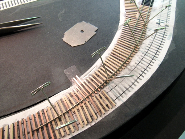
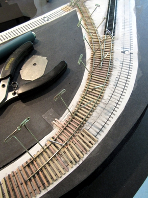
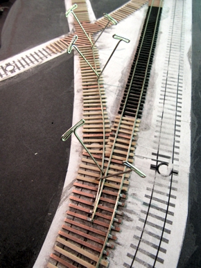
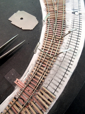
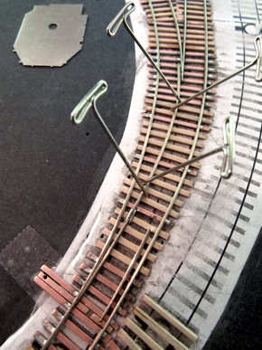
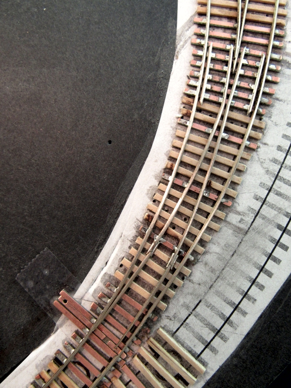
Before cutting any ties or rails, I established the design rules. Because the turnouts are all quite small, I wanted zero-stress jointed points—that is, instead of soldering the points to the throwbar, they're linked to it with pins so they can freely pivot. Additionally, the points pivot on the ends of the closure rails, instead of being one piece that's bent into position. And finally, I wanted to build the turnouts in situ on the layout, rather than at the work bench, to reduce the number of rail joints to an absolute minimum.
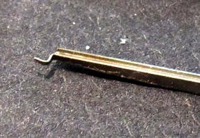
The point-to-throwbar connection was key, and I test-built a set of points as proof-of-concept. First, I ground ~0.080" of the head and web off the end of a piece of rail, leaving only the base. Then I ground the point taper, leaving a narrow slice of the base at the end. After bending the base down at 90°, I inserted it into a #75 hole drilled in a PC board throwbar (below left, top), then bent it up into a relief ground on the underside of the throwbar (below left, bottom) to form a Z-shape (below right). Finally, I clipped the very end flush with the side edge of the throwbar. The points easily slip in and out of the throwbar when held at a high angle, but can't be removed once they're horizontal.
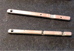
Here's an illustration for clarity. The top half shows the parts, and the bottom half shows how they're assembled. The other end of the points fit into rail joiners cut in half and soldered to the ends of the closure rails. I'd simply pop the points into the throwbar just before I soldered the closure rails on the ties, after which time all of the parts are permanently locked in place.
I wanted to have as few rail joints as possible, so I used flex track rail for the turnouts so they were contiguous by stripping off ties at the ends of the flex. But the distance from any one turnout to the next nearest one was always less than the length of flex track, which meant I needed to have all of the ties down for all seven turnouts before building any of them. So my first day of tracklaying was spent just bonding ties in place.
I bonded the ties in place with brush-on Krazy Glue, all spaced by eye. Any concerns I'd had about the bonds not being strong enough were completely dispelled when I tried to remove some, and destroyed them in the process. As I learned, the CA bonds the PC boards to the paper template very well, and as the CA soaks into the paper, it further bonds with the Gatorfoam underneath. Those ties aren't going anywhere!
A Turnout A Night
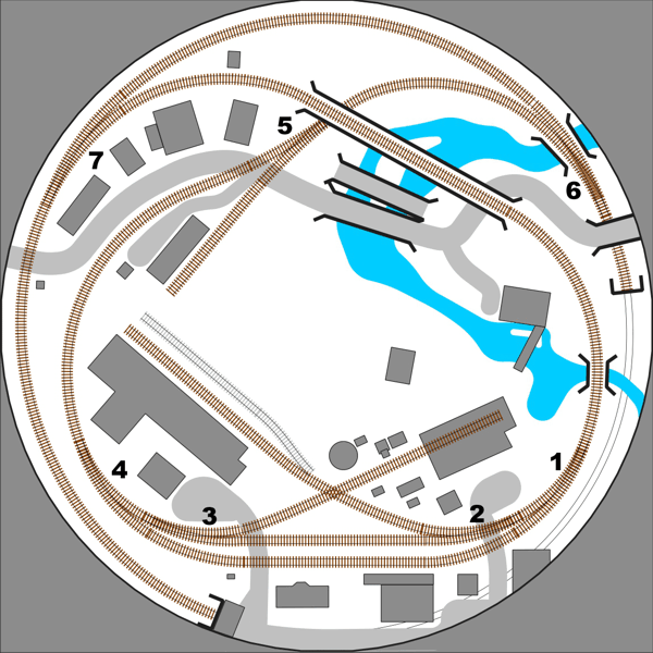
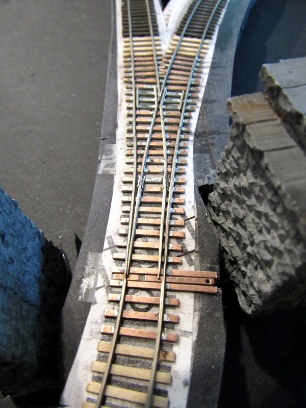
With seven turnouts to build, I figured it would take me about a week to build them all. However, after building #3 and #5 on the diagram below, I got distracted doing other things in my typical ADD fashion. At my current rate, it'll be months before I finish.
It took the better part of a day to finish the first handlaid Code 40 turnout I've done in a good 20-25 years, which was #3. One thing that helped immensely was positioning the rail with T-pins, rather than simply holding the rail with tweezers, as I used to do; I could position the rail with surprising accuracy with the T-pins.
My second turnout, #5, took only a few hours. I did this one next mainly because I wanted to hurry up and install the steel trestle so I could finish laying the flex track.
Turnout Operation
Originally I'd planned to control the turnouts manually using the system I'd devised for the Mountain Vista Railroad: it was simple, economical, and worked perfectly. But given that I'd have a separate control panel, I switched to powered turnouts. Furthermore, I built my own switch machines, which was no big deal—I have dozens of geared motors and hundreds of surplus microswitches on hand I'd otherwise never use.
|
|
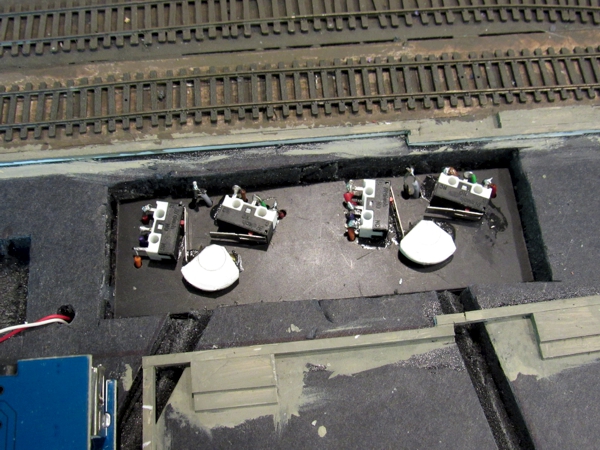
The geared motors I had came with magnetic clutches, which I didn't need, but the discs to which the magnets were attached made perfect cams to actuate microswitches. My "homemade Tortoise" comprises a motor and two microswitches, one to control the motor and one to change the frog polarity. Also connected to the cam is a steel wire to throw the points. The motor is actuated by a SPDT toggle switch.
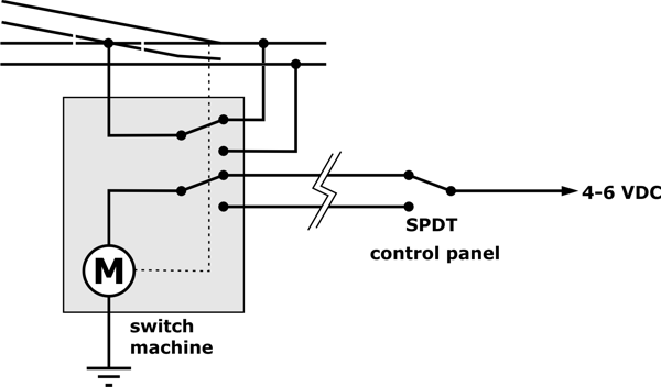
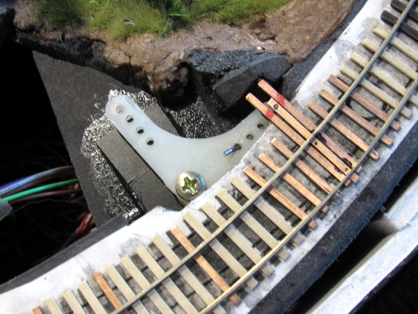
The method of powering each turnout was a little different, and some were quite different. For instance, owing to its proximity to the lily pond, turnout #1 required a bell crank to rotate the motion 90 degrees.
The switch machines for turnouts #3 and #4 are hidden under the fireworks factory.
|
|
Incidentally, I'd planned to power the turnouts on the original layout with homemade slow-mo machines powered by nichrome wire. It was an obscure concept back then and may be even more so now: the nichrome is stretched along a frame, and connected to a lever on one end that's linked to the turnout throw bar. When the wire is energized, it heats up, expands, and moves the lever, thus shifting the points. I'd collected all of the raw materials I needed to build all of the mechanisms, but never assembled them.