7. Taking Control
The Control Panel
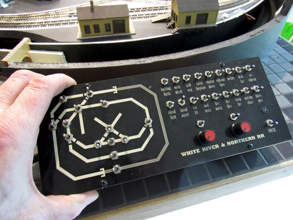
Except for the size and the sea of animation switches, the panel bears a striking resemblance to the one I built for the original layout. That one I made from ¼-inch Plexiglas, which I masked and painted from the back, resulting in a very robust and durable panel. This time, as per my new SOP, I rendered the panel art in CorelDraw, and printed it on self-adhesive stock that I laminate with plastic for durability.
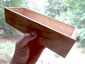
Although I used the same technique, this time I used different materials than I normally do. I discovered a stash of label supplies that included matte finish transparent. I printed the art on the clear label, then applied it to self-adhesive sheet vinyl, and instead of plain white, I used an off-white color that gave the panel a vaguely antique-ish quality. Then I applied clear laminating film over that for a durable and attractive panel face. Meanwhile, I assembled a 2 inch deep control panel box out of scrap lumber (below left and right).
The panel itself is a piece of ⅛"-thick black sheet styrene measuring 4 by 10 inches. After drilling all of the switch holes, I applied the artwork, finished assembling the control panel, and attached it to the wooden box (below).
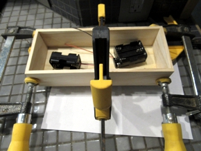
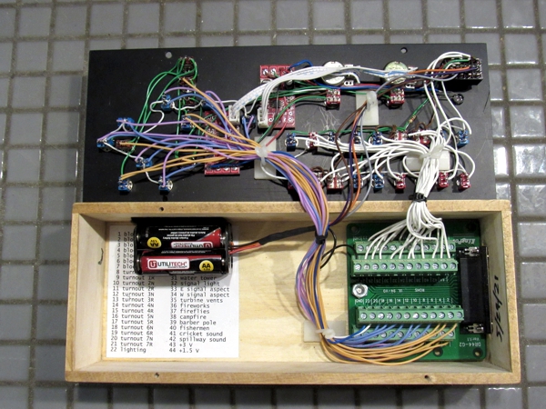
Begun in late May, the control panel was completed—including the throttles and power supply—on the first of July 2021. Below, I've spilled the guts for all to see. The battery pack is held in place with a strip of Velcro.
The DB44 jack is mounted such that the plug neatly sits flush against the side of the box when connected.
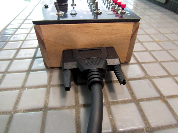
The other end of the cable jacks into the layout.
Who Goes There
Even though it's unlikely I'll be operating two trains simultaneously, I have nevertheless wired the layout for dual-cab control mostly for the sake of nostalgia—it's how I wired the original. Back then I was proud of the fact that I understood the cab concept, and wired the layout accordingly.
Below is the block map, which I numbered starting at the enginehouse, working clockwise around the whole layout. 1A and 4A just have on-off kill switches to park a train. Gaps are clearly marked with thick black lines.
Turnouts are likewise numbered starting at the enginehouse, and working clockwise around the whole layout.
Getting Connected
 As I developed the layout, I tried to envision how I'd
control things, starting with the turnouts. At first I
was going to operate them manually, using the same system I'd devised for the Mountain Vista Railroad. However,
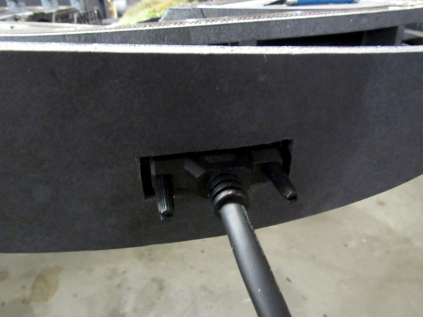
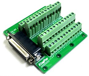
as I thought about lighting and effects, I realized there was no convenient place for any of those controls. So, I retrieved the connector I'd
purchased for the Newport & Rock Falls II and never used—a DB44 breakout board and socket
(right). A quick calculation confirmed it would be just large enough to support everything, including the animations
I've been considering, even assuming I used all of them. Below, I cut an access hole in the trim for the DB44 cable.
As I developed the layout, I tried to envision how I'd
control things, starting with the turnouts. At first I
was going to operate them manually, using the same system I'd devised for the Mountain Vista Railroad. However,
as I thought about lighting and effects, I realized there was no convenient place for any of those controls. So, I retrieved the connector I'd
purchased for the Newport & Rock Falls II and never used—a DB44 breakout board and socket
(right). A quick calculation confirmed it would be just large enough to support everything, including the animations
I've been considering, even assuming I used all of them. Below, I cut an access hole in the trim for the DB44 cable.
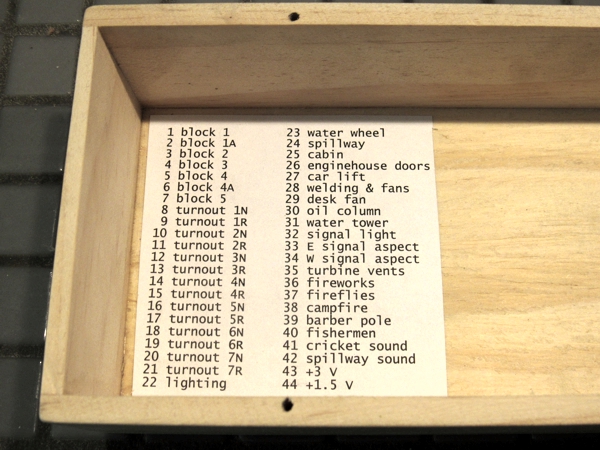
Inside the control panel is another breakout board. To help keep track of things, I printed a list of the cable pinouts on label stock and mounted it inside the panel box.
Throttles and Power
As per usual, I'll make my own throttles, and use batteries to power everything. The batteries will live inside the control panel box.