Working with Rokuhan Switches, Part 4: Making Them Non-Power Routing
Rokuhan Z Scale roadbed switches are marvels of engineering. The fact that the switch machine is built into the roadbed is remarkable in itself; however, there's far more to it than meets the eye. The more you know about them, the more powerful and versatile they can be. This comprehensive clinic has four parts: Part 1 shows how to control them; Part 2 details what power routing means to layout design; Part 3 shows you how to notch track that's connected to the switch; and this part details the process of making them non-power routing.
Some modelers prefer having their switches inherently non-power routing, or in other words, "power everywhere," just like Micro-Trains switches. (See Part 2 for an explanation of what power routing means.) Rokuhan posted a video demonstrating how to do this. The only problem is that it requires soldering, and some modelers would prefer to not solder joints on postage-stamp-sized PC boards.
So, here's how to do it without soldering; instead, you'll just need to make four small cuts in plastic with a sharp knife. Another advantage of this method is that it's easily reversed, in the event you need to change the switch back to power routing. This clinic will also demonstrate how to completely dismantle a Rokuhan switch all the way down to every last part, just in case repairs are needed (although this should be extremely rare).
What you'll need: a #0 Philips head screwdriver, a pair of tweezers, a sharp knife, a test meter, and some fine bare wire.
Disassembly
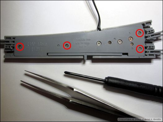
Begin by removing the four screws circled below. Do not remove any of the other screws.
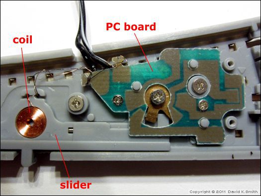
After removing the cover plate, inside you will see the coil, which fits in the slider, and the PC board.
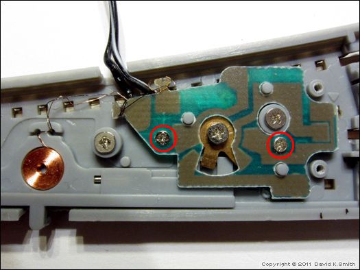
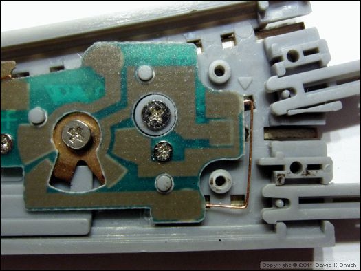
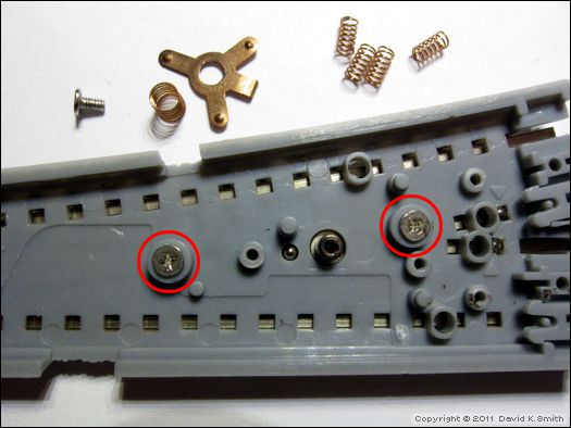
Remove the two screws holding the PC board in place; they are circled below. Then very carefully remove the PC board, as well as the slider.
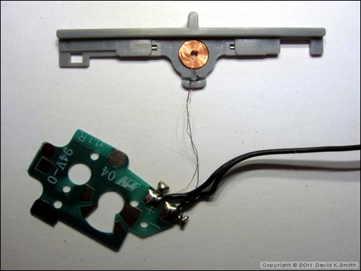
IMPORTANT: The wires from the coil are connected to the PC board, as shown below. These wires are very fine and easily broken; handle these parts with extreme care.
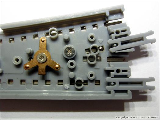
You will now see the rotating switch contact, and four springs. The springs pass current from the PC board to the rails.
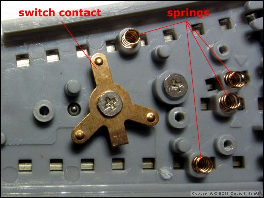
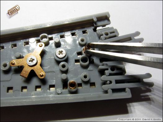
Using a tweezers, remove the springs and set them aside safely.
Modification
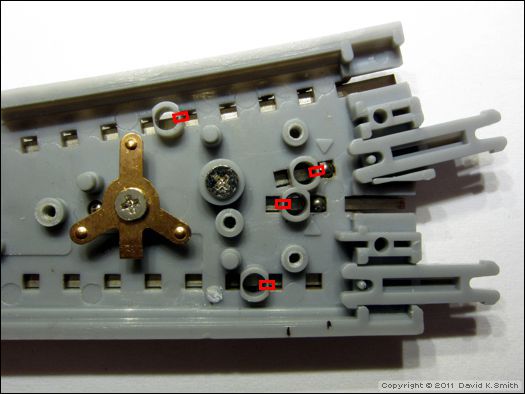
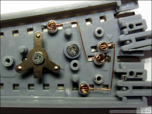
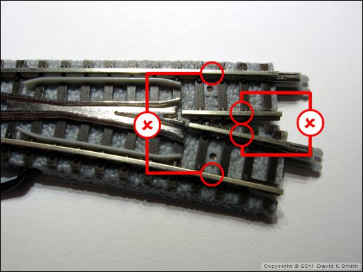
In order to make the switch power everywhere, a pair of jumper wires must be added between pairs of springs. Small notches need to be cut into the spring enclosures to accommodate the jumper wires. The notches should be oriented as shown below:
Make the notches with a sharp knife.
Clean up all cut edges. This is how the switch will look when finished:
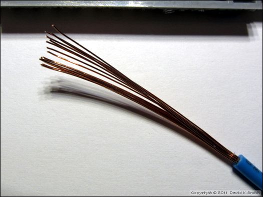
Fine bare wire is needed for the jumpers, and a good source is ordinary stranded wire. Strip off about an inch of insulation (below) and clip off a few of the wires.
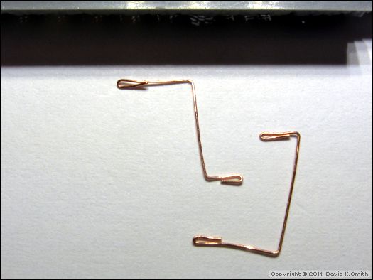
Using a tweezers, form two pieces of wire into the shapes shown below. The loops on the ends ensure good contact with the springs.
Re-insert the springs into the notched enclosures.
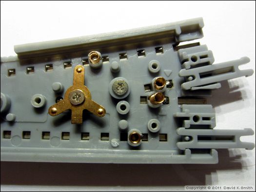
Carefully insert the jumper wires through the notches and into the spring enclosures as far as they will go.
Replace the slider and PC board, ensuring that the PC board is seated completely.
Reassembly
IMPORTANT: Before reassembling the switch, perform these checks:
1. Ensure the switch contact tab properly engages the square hole in the slider, as shown below.
2. Using a test meter, verify there is continuity between the stock (outer) rails and the corresponding rails leading from the frog. Repeat the tests with the switch set to both positions.
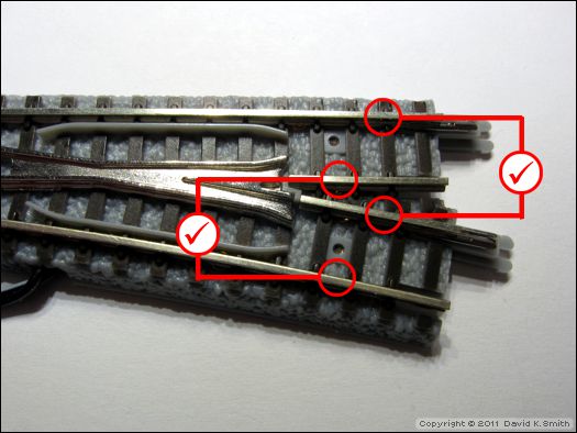
3. Verify there is no continuity between the two stock rails, and no continuity between the two frog rails. Repeat the tests with the switch set to both positions.
4. Ensure the wires from the PC board to the coil are not tangled, and that the slider moves freely from one position to the other.
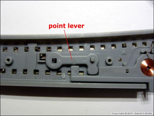
5. Ensure the point lever properly engages the tab on the points and the slot in the slider.
Replace the cover plate to complete the procedure. Test the switch under power to ensure proper operation.
Complete Disassembly
Should it be necessary to completely disassemble the switch, follow these steps. (This sequence picks up where the previous procedure left off, after removing the cover plate and the PC board.)
Remove the switch contact retaining screw, the contact, and the spring, then remove the two frog attachment screws, circled below.
The frog can now be removed from the roadbed.
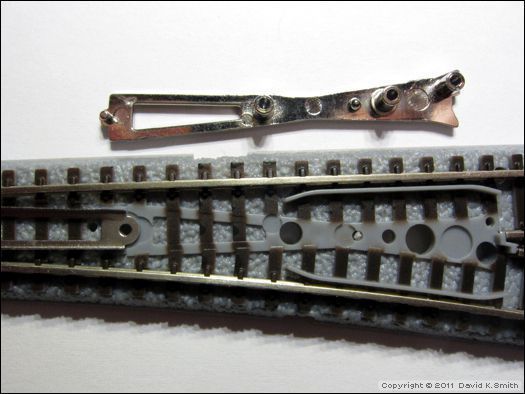
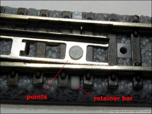
The points cannot be removed without altering the roadbed part. The reason is that a retainer bar is permanently attached to the points, as shown below; this retainer bar keeps the points from lifting up from the roadbed.
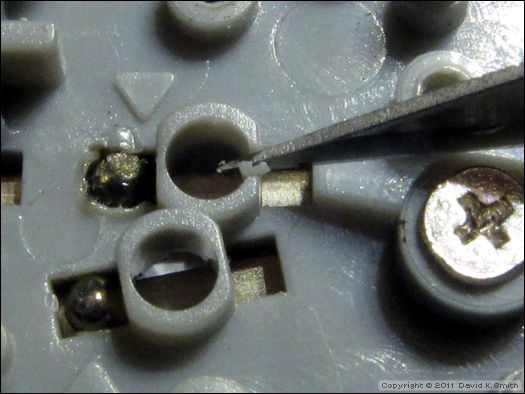
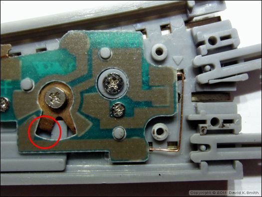
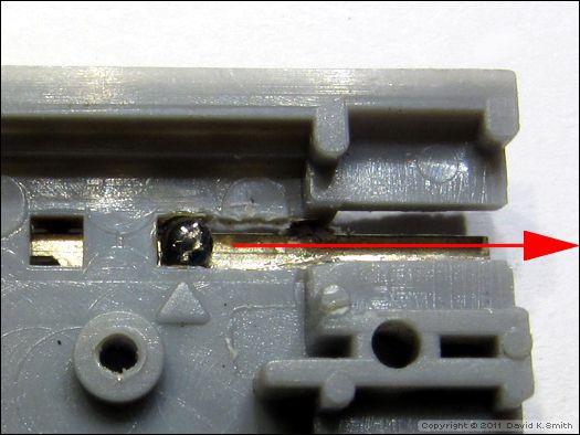
In order to remove the points from the roadbed, one of the stock rails must be extracted. This requires cutting a small notch in the roadbed just to the right of the rail index pin (silver sphere) on the straight stock rail at the point end of the switch, as indicated below.

After the notch has been cut, the stock rail can then be slid out of the roadbed in the direction of the arrow.
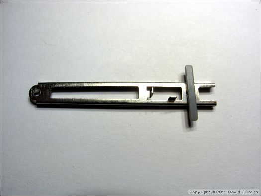
Once the stock rail is extracted, the points are free to be removed. You will notice how the retainer bar is permanently attached to the points; the bar cannot be removed without cutting it, making repair a challenge.
Reassembly
Follow the disassembly procedure in reverse, starting with the points. After carefully sliding the stock rail back in place, secure it with a small drop of CA on the index pin.
IMPORTANT: As you reassemble the switch, perform these checks:
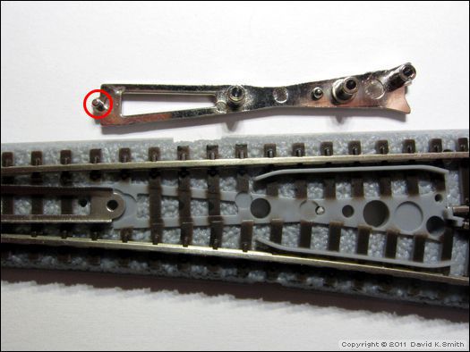
1. When reattaching the frog, be sure the pin circled below fits properly into the hole in the end of the points, and that the hole in the points is aligned over the corresponding hole in the roadbed.
2. When replacing the rotating switch contact, be sure to include the spring that fits under it.
3. After the switch contact screw is fully tightened, ensure the contact rotates freely.
4. Ensure the switch contact tab properly engages the square hole in the slider.
5. Ensure the wires from the PC board to the coil are not tangled, and that the slider moves freely from one position to the other.
6. Ensure the point lever properly engages the tab on the points and the slot in the slider.
7. If the switch has been electrically modified, perform the continuity tests as detailed previously.
8. Test the switch under power to ensure proper operation.
If you have any questions on working with, modifying or repairing Rokuhan switches, do not hesitate to contact me.
More Information
To learn more about working with Rokuhan switches, please begin with Part 1.
![]()
![]()
![]()
![]()
Copyright © 2007-2013 by David K. Smith. All Rights Reserved.