Working with Rokuhan Switches, Part 2: Power Routing
Rokuhan Z Scale roadbed switches are marvels of engineering. The fact that the switch machine is built into the roadbed is remarkable in itself; however, there's far more to it than meets the eye. The more you know about them, the more powerful and versatile they can be. This comprehensive clinic has four parts: Part 1 shows how to control them; this part details what power routing means to layout design; Part 3 shows you how to notch track that's connected to the switch; and Part 4 details the process of making them non-power routing.
Frogs and Points
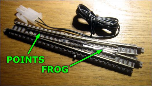
Before diving into the nitty-gritty, here's a micro-primer on the parts of a switch. The two parts that are referenced in this article are the points (the rails that move to change routes) and the frog (where two rails cross one another). To help you visualize these parts, refer to the image below:
Power Routing versus Power Everywhere
You may have seen these terms used in reference to various track switches, and you may have no clue what they mean. Allow me to help.
Power Routing means that, when a track switch is thrown in one direction, only that track receives power to run the locomotive; the other track is shut off. So, if there's a train on both tracks, only one of them will run—the one on the track to which the switch is aligned.
Power Everywhere means that all tracks receive power, regardless of the switch position. So, if there are trains on both tracks, both will run, regardless of which way the switch is thrown.
There are pros and cons to each design. Power Routing switches have the advantage of being able to park trains on sidings without having to wire them with toggle switches to control track power. Even more importantly, Power Routing can prevent trains from entering switches that are thrown the wrong way, thus preventing derailments. The downside is having to wire a layout properly so that trains are not unintentionally shut down by a thrown switch; this is just a matter of paying more attention to where track power feeders are located.
Power Everywhere switches are better suited for DCC-based layouts, where the throttle is in complete control of a locomotive instead of switches or control panel toggles, because Power Everywhere switches prevent portions of a complex layout from losing power. The downside is that (on non-DCC layouts) you'll need to add insulating joiners, extra track feeders and toggle switches in order to park trains on sidings. It's also very easy to run trains against switches the wrong way and cause derailments.
Which Is Better?
Of the two options, one has a distinct advantage over the other as being the better choice. The answer is Power Routing.
Here's why: let's assume you have a preference for the Power Everywhere option, but you have a Power Routing switch. You can turn a Power Routing switch into a Power Everywhere switch by simply adding track power feeders to all of the tracks connected to the switch.
Now let's look at the reverse scenario: let's assume you prefer Power Routing, but you have a Power Everywhere switch. You have two options, and they're both difficult and complicated. One is to modify the switch—this means taking it apart and cutting/grinding parts of the circuit to change it's behavior. The other option is to assemble an extra electrical circuit for each track you want to control using either toggle switches or (if you don't want to have to remember to throw the toggles) special twin-coil relays, which can start getting complicated and expensive.
Layout Wiring
In order to take advantage of Power Routing switches correctly, you need to be mindful of how you wire a layout. You can't connect track power feeders to any arbitrary location, as you can with Power Everywhere switches; there are rules to follow in order to ensure your trains receive power the way they should.
Consider the simple layout shown below. When it's built using Power Everywhere switches, you can connect track power to literally any location on the layout—even the end of one siding—and track power will still flow to every piece of track.
Note, however, that if you wanted to park a train on one of the sidings and run another train on the loop, you'd need to add an insulating joiner at the switch, connect another track power feeder, and also wire an on/off toggle into the circuit.
Now let's look at the same layout built with Power Routing switches. Assume the track power is connected at the arrow, near the upper left of the plan. When Switch A is set to the straight route, the two sidings have no power. A train will only run on the outer loop.
If Switch A is set to the sidings, and Switch B is set to Siding 1, Siding 1 will have power and Siding 2 will not. (Note that the straight route at Switch A still has power because the track is connected in a closed loop.)
If Switch A is set to the sidings, and Switch B is set to Siding 2, Siding 2 will have power and Siding 1 will not.
Notice that you can park a train on either siding without having to add insulating joiners, wire toggle switches or do any extra work at all; the Power Routing switches do all of the work for you, automatically.
Now, to illustrate what can go wrong, let's instead connect track power to Siding 1. If Switch B is not aligned to Siding 1, track power will not be able to reach the rest of the layout.
To prevent problems like this, just remember one simple rule for Power Routing switches: always provide track power from the point end (single leg) of the switch. Otherwise, you could wind up in a situation where trains won't run.
Passing Sidings
A special case to consider is a passing siding, where there's a switch on both ends of two parallel tracks. In this case, the track with which both switches are aligned will receive power, whereas the counterpart will be dead.
Now let's see what happens if one switch is thrown to one track, and the second is thrown to the other: both tracks will be powered (the same way it would be using Power Everywhere switches).
However, what if you wanted both switches to control track power, regardless of their relative positions, in order to park trains or prevent derailments should a train run against the switch? In this case, the problem is solved by adding an insulating joiner on one rail of each of the two tracks, positioned around the middle of each length of track.
Now you can park a train (as long as it's located beyond the insulated joiner) and, more importantly, protect the switch from derailments.
IMPORTANT: When adding insulating joiners for this purpose, remember this rule: insulating joiners must always be on the same rails as the switch frogs. Otherwise it won't work. (The reason is that the outer two rails of a switch are continuous, and will always conduct power to the tracks connected to it.)
Let's see how we can use this same trick to modify the example layout shown above. Say we want to protect Switch A from possible derailments when it's thrown against a train on the outer loop. Add an insulating rail joiner to the track at the location shown below, and now the switch is protected when it's aligned with the sidings.
Again, remember to place the insulating joiner on the same rail as the switch frog; otherwise, the switch will not be protected.
Power Where It's Needed
Rokuhan makes it really easy for you to deliver power to the track where it's needed. There are no special power feeder track sections in the Rokuhan line; instead, all of the 110mm and 220mm straight track sections have a removable insert. Simply slide it out, and pop in a track power feeder, Rokuhan part #RKA001. Need longer wires? The extension is #RKA003. (See all of the available track and accessories here.)
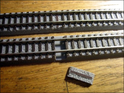
Adding Gaps
Rokuhan is planning to introduce an isolating rail joiner, part no. A013. This is a plastic piece that replaces both of the metal and plastic joiners, electrically isolating both rails. The product has not yet been released, so in the meantime, you can use Atlas #2091 plastic rail joiners. They're made for their N Scale Code 55 track, but they work perfectly on most brands of Z Scale track, including Rokuhan. Simply remove both plastic and metal rail joiners, replace the plastic joiners, and then slip the Atlas insulating joiner onto the rail in lieu of the metal joiner (below).
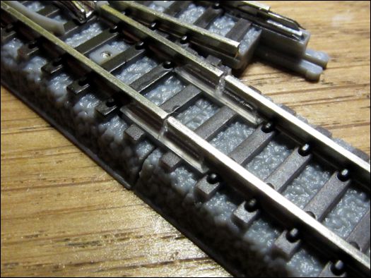
Physically cutting the rail to create a gap is not recommended. Because of the way the track is assembled, it will leave one portion of the rail free to slide out of the plastic roadbed. It would then need to be bonded in place, with no assurances of good, permanent alignment. Therefore, plastic joiners are strongly recommended over cutting the rail.
Best of Both Worlds
Rokuhan reportedly may be redesigning their switches to provide modelers with the option to choose how the switch works, similar to the way newer Kato Unitrack N scale switches are designed. It will likely entail turning a small screw on the underside of the switch to select the behavior. Until that day arrives, simply refer to the above information on how to work with Power Routing switches.
In the meantime, if you prefer having power-everywhere switches, it's not difficult to modify Rokuhan switches to behave that way. For details on how this can be done, refer to Part 4.
More Information
To learn more about working with Rokuhan switches, please continue with Part 3.
![]()
![]()
![]()
![]()
Copyright © 2007-2013 by David K. Smith. All Rights Reserved.