
Switch Building Test Although the previous tracklaying test served its purpose well, I felt the need to go one step further before jumping headlong into the layout itself, and build a switch. This would not only allow me to perfect the process of making functional narrow-gauge switches, but also force me to set standards such as flangeways. Sooner or later I'd need to face this issue, so now seemed the best time. The other thing I wanted to try was making my own ties, perhaps even using something other than PC board. The previous test highlighted a potential problem: the inconsistency of the Fast Tracks PC board ties, however slight, left me a little uneasy, as my need for precision is quite a bit higher than the norm. The smaller the scale, the tighter the tolerances, and Z is already small enough—three-foot narrow gauge just makes things that much worse. My new choice for tie material was a radical departure: .045-inch solid brass square rod stock. I can imagine some readers suddenly sitting up straight in their seats and yelling at their monitors, "Are you insane? Think of the cost!" Well, actually, the financial cost is almost trivial—Z scale narrow-gauge ties are really short, after all—and it cost me nothing to get started as I already had a fair amount of suitable stock on hand, courtesy of one of those K&S grab bags. No, my friends, the insane cost involved is time. Consider: every tie would need to be split into two—and some in three—separate pieces to electrically separate the rails; these tie parts would be soldered individually to a roadbed made of solid PC board. Plus, each part of the three-piece ties had to be cut to fit individually—they couldn't be pre-cut. As an example of the absurd amount of effort involved, the three-piece ties required no less than 29 assembly steps; the first one took about ten minutes to complete (naturally the time dropped as I got into a rhythm, but not by much). Incidentally, one might be tempted to think that, owing to the somewhat irregular placement and spacing of the ties on the real railroad, which I'm reproducing faithfully, I'd have marginally less work. However, this does not happen to hold true; because the ties are all split, accuracy of their placement is still critical. This can perhaps be described as "precise imprecision." The first step was to make the roadbed, which I cut from a 1/16-inch thick sheet of plain single-sided copper-clad PC board. I marked the outer perimeter of the roadbed with a pencil, cut the piece out using a coping saw, then, with a sanding drum on a Dremel tool, I ground the edges of the PC board strip to an angle roughly approximating roadbed slope.
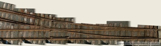
The PC board roadbed was bonded to a chunk of 1/8-inch thick sheet styrene with thick CA, and clamped in a smooth-jaw vice to ensure flatness (above). Then, using an X-Acto knife and a printed photo of a 1:1 switch (below), I traced all of the rails onto the surface of the PC board so that I could plot where the cladding had to be split. To split the cladding, I scored it with the knife held backwards, and sanded it smooth; then, using another copy of the photo template, I marked the position of each tie on the copper.
Then began the tedium. After cutting a bazillion brass tie pieces to length and sanding their ends smooth, I carefully soldered each piece in position on the PC board (below). This took seemingly forever; it's good that, what I may lack in spare time, I make up for in patience. Tie part pairs were separated by bits of paper during soldering.
Oh, and here are those 29 steps for making each of the 21 three-piece ties:
With all of the tie soldering done at long last, I flipped the assembly over and sanded all of the ties true on sanding film secured to a smooth work surface. This time I could be as aggressive as I needed to, since I was not about to wear any cladding away (above).
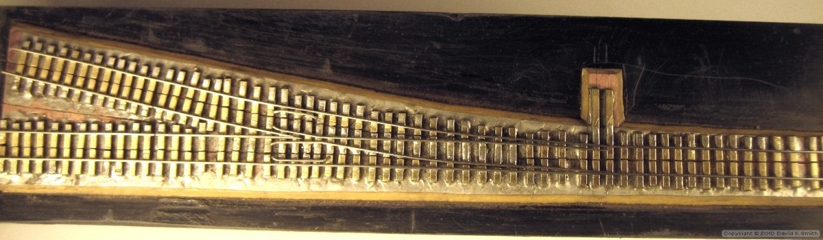
Then at last it was time for tracklaying. I began with the straight stock rail. Soldering was much slower-going than before since the solid brass ties and copper roadbed acted like heat sinks. However, once the rails were soldered in place, I was able to do much more aggressive cleanup than I could with PC board ties—which is a good thing, because there's a lot more excess solder to remove after soldering the rail to solid brass ties. This alone had me thinking I was perhaps taking the right approach. For a track gauge, I filed a piece of brass down to .164 inches long (36 Z scale inches) and simply placed it between the rails (above). With both stock rails in place, I turned my attention to the points. Ordinarily they'd be portions of rail left unsoldered, and simply bent into position by the throwbar. But given their tiny size, I imagined they'd be too stiff to flex easily, which might create issues with the throw rod. So, I employed the technique I used for a T Gauge switch I'd built, which resulted in points that moved just like the real ones.
The points are separate lengths of rail, ground with a Dremel to a taper, and soldered endwise to pieces of .015-inch diameter steel wire oriented vertically to the rail, making an inverted L-shaped assembly (above). The wires drop into holes drilled in the ties; below the subroadbed, they're are bent at 90 degrees and will eventually engage a mechanism to position and move the points. Thus the points do not need to even be attached to the throwbar, avoiding altogether the primary Achilles heel in small-scale handlaid switches: the point/throwbar connection. The throwbar can simply be simulated, using most any material, even styrene, allowing it to be modeled much more realistically—which is a very good thing indeed because there would be no practical means to attach anything to the ends of these points!
The points were ground, assembled and installed (above) before proceeding with the frog (below), because it's easier to precisely align a rail with a drilled hole, as opposed to drilling a hole that precisely aligns with a rail. Then the the frog and guardrails were cut, shaped and soldered in place. But before I could do that, I had to decide on my wheel standards. Thinking about what I could possibly make by hand, I settled on ~.008-inch wide by ~.010-inch deep flanges. Thus, I placed the guardrails around .010 inches from the stock rails, using a sheet metal shim to position them.
By the way, the finished guardrails may look mismatched and misplaced, but they mimic the real ones (above), within the scope of practicality given that the model frog geometry is different owing to the larger flangeways. With the switch fully assembled, I flipped it over and sanded the railheads true, just as I had the ties.
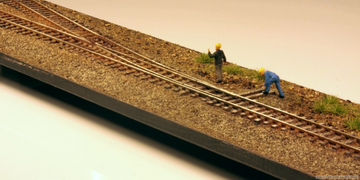
The final steps involved finishing. First, I filled in the tie gaps with thick CA; this took a few applications. After giving everything a final scrubbing with a wire brush, I applied a few light coats of spray primer. Following my usual procedures, I brushed on accent colors, washes and rust patinas. Then, after applying a little light oil to the points to make them easier to free up, I ballasted the track. Some ground cover, vegetation and figures completed the micro-diorama (below; click to enlarge).
While the results exceeded my expectations, I'll confess that the thought of doing all of this 14 times over for the layout was a bit sobering, and for once I was thankful for my acute space limitation—I certainly couldn't imagine doing a full-sized layout this way!
|


Copyright © 2010 by David K. Smith. All Rights Reserved.