
Tracklaying Test Given that I'm venturing into uncharted territory—namely true American three-foot narrow-gauge in Z scale—I felt that I would benefit from performing a little tracklaying test. I'd done this for my James River Branch layout, and it was a valuable exercise. I pretty much knew in advance how I would approach tracklaying this time around, and some things would be different, mostly because the tracklaying had to be far more precise this time around. The need for precision is governed by several factors. First, all of the rolling stock would be scratchbuilt from the ground up, and I sensed I would not be able to build mechanisms that would be as forgiving of track geometry issues as commercial locos in larger scales. Worse, some of the locomotives would be rigid-framed, short-wheelbased steamers, and the only way these would run reliably was if the track were flawless. Compounding the problem was my desire for the very best possible appearance, meaning fine flanges and narrow flangeways. This need for precision tracklaying pretty much excluded the use of a foam tape roadbed, so, I planned on bonding the ties directly to a thick sheet styrene roadbed, which would be firm and true. I also planned on using Fast Tracks Z scale ties. As a stroke of luck, their ties measure 18 scale feet long, and since average three-foot-gauge ties are about 6 feet, I could get 3 finished ties out of each uncut tie, with no waste.
Getting to work, my first step was to chop up some ties (above). Then I cut out a rectangular scrap of .080-inch thick styrene. Using a mechanical pencil, I marked a pair of parallel lines spaced 0.164 inches (three scale feet) apart along the length of the styrene. It was at this point I started taking shorter breaths: those lines were awfully close together! But after a time it began to feel a little familiar.
I bonded the ties to the styrene with Krazy Glue bush-on thick CA—my CA adhesive of choice these days—positioning them by eye with tweezers (above). To look at some of the 1:1 track (below), one might suspect they positioned the ties by eye as well... Placing ties was made more tedious than expected because the ties have "good" and "bad" sides, and each tie had to be placed good-side up. But to ensure a firm bond, the bad side also had to be lightly sanded. I imagined doing this for the whole layout—even as small as it is—and a sinking feeling started setting in... what was I getting myself into? I couldn't think about that; I had to press on.
Once the ties were down, I sanded them firmly with 320 grit sanding film on a block to get their surfaces all true, to ensure the rails would likewise be true. The need for this step immediately became apparent as I began sanding, as a few ties were well-polished while the remainder weren't even touched. But I couldn't be too aggressive, or I'd lose some of the copper altogether (which I did on a couple of ties). Finally came the moment of truth: soldering the rails in place. Thankfully I'm no stranger to this process, although I'd need to amp up my accuracy several notches. I'd originally ordered it for use in N scale, but it turns out it's even more useful in Z, where much finer rail is needed for realism, yet none exists commercially, not surprisingly—how many lunatics like me willing to hand lay Code 25 track are out there?
After applying Stay-Clean liquid flux to the rail and ties, I held the rail vertically in place with tweezers, and soldered it to every eighth or tenth tie so that the rail would remain in position on its own (above). Then I went back and soldered the rail to all of the remaining ties, working hard to ensure that I got an absolute minimum amount of solder on the joint—this is the single biggest challenge of the process. A frequently asked question is why do I use all PC board ties, instead of the usual technique of a PC board for every sixth or eighth tie, and conventional wood ties for the remainder. The answer is two reasons: one, Code 25 rail is very delicate, and it needs the strength of all the solder points it can get; and two, the wire has no base (in fact, the edge is rounded), so it needs additional support to maintain the proper orientation.
To gauge the second rail, I made spacers from scraps of laser kit micro-ply sanded to .164 inch width, placed the spacers against the first rail, placed the second rail against the spacers, and held everything together with self-clamping tweezers (above) until the second rail was tacked in place. After removing the spacers, I completed all of the solder points on the second rail. Finally, I scrubbed the track with a wire brush to remove any loose material, then cleaned it thoroughly with soapy water to remove all traces of flux.
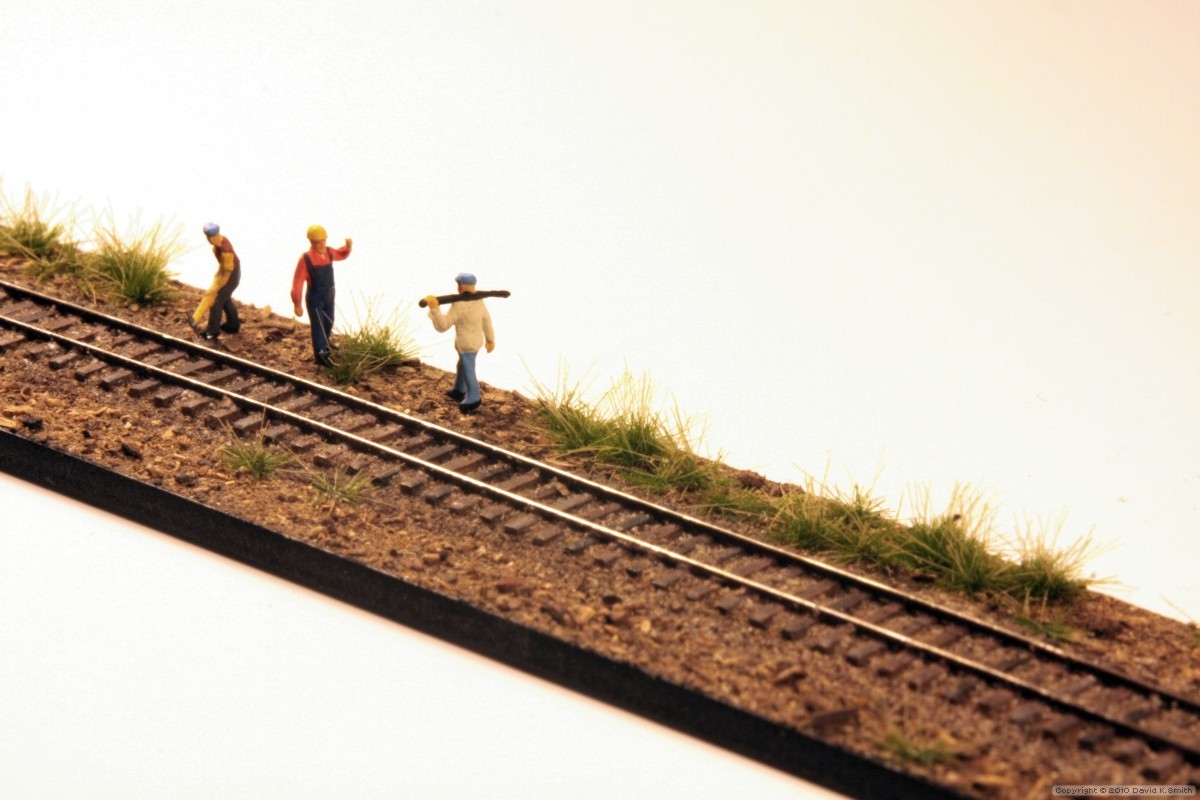
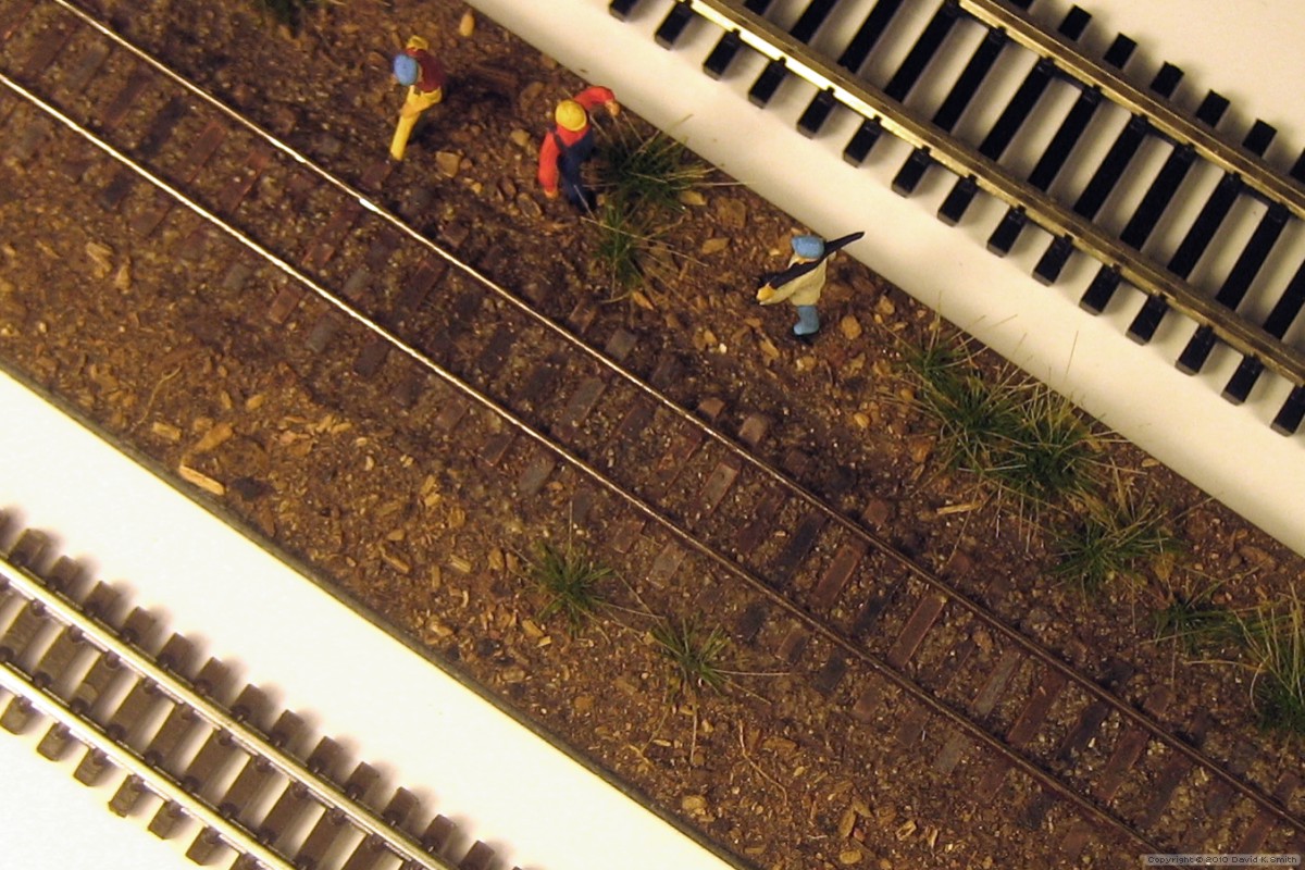
Although I was reasonably satisfied with the results (above), I was a little disappointed at not having anything to roll down the track! But this acid test must wait for another day; meanwhile, I decided to paint and ballast the test track just for kicks: I sprayed the assembly with Floquil Roof Brown, brushed India ink and Driftwood stains onto individual random ties, and streaked the rails here and there with a little Rustall. Finally, I ballasted the track with minitec 50-0011-01 ballast, cleaned the railheads, then added groundcover, some weeds, and a couple of figures to help provide a sense of scale.
Here's a comparison: top right is Micro-Trains Z scale standard-gauge flex track; bottom left is T Gauge (1:450) flex track.
|


Copyright © 2010 by David K. Smith. All Rights Reserved.