Bashing Brass Buildings, Part 1 of 3
by David K. Smith, 30 August 2008
 By
and large, modelers kitbash styrene structures; however, North American Z-scalers are limited in what we
can do in styrene, given that we have no American styrene structure kits! Unfortunately the market size
isn't big enough to support the investment required for the injection-mold tooling.
Thus, scratchbuilding aside, we're left with the following options: Americanize European kits (getting old), cobble things together from laser-cut wood kit parts (presently limited but improving), or kitbash etched brass (challenging).
Given what's available, I'll take challenging, which in certain circumstances is the only option: if you're modeling a Northeast American town, as I am, just about the only source for classic urban structures is Miller Engineering. Their fine "Micro Structures" kits are all etched brass—an economical alternative to injection-molded styrene for the manufacturer, but a real challenge for the modeler looking to move beyond stock kits.
Tools and Supplies
Kitbashing in brass may sound quite daunting, and indeed I approached it with some trepidation given that, for starters, I'm not all that great at soldering. Bashing brass does require a substantially different skill set from the norm, and it also takes more tools than you'd need when working in styrene, where 98% of the job can be done with a hobby knife. To give you an idea, here are the tools and supplies I'll employ in a typical brass project:
- thermostatically-controlled soldering iron with a fine pencil-tip
- electronics-grade solder
- soldering flux (I prefer Stay Clean liquid flux from Micro-Mark)
- motor tool (Dremel or equivalent) with cutoff wheel and wire brush
- pin vice and drill bit set
- jeweler's files (flat, square, etc.)
- sandpaper in a variety of grits
- flush cutters (rail nippers)
- flat-jaw pliers
- hobby knife and lots of extra blades
- tweezers, regular and "reverse" spring-loaded
- heavy-duty paper cutter or metal shear (optional)
- steel straightedge
- steel triangle
- cutting mat
- masking tape
- spray paint
- paint thinner
- various paint brushes
- ceramic or glass dish
- plastic containers
- Foamcore and heavy cardstock scraps
- thick cyanoacrylate
- white glue
In theory you could use cyanoacrylate adhesive in lieu of soldering for all joints; however, glued joints require much more substantial bracing than what's needed for soldering, since CA is nowhere near as strong or reliable. In fact, some joints that I've made using solder could not have been accomplished any other way. That said, some joints are impractical to solder because of the size or shape, the proximity to other solder joints, or the fact that the joint is on the face of the structure, and in such cases CA is indispensable. Also, CA is used to join painted and finished subassemblies.
Note that I didn't include a bending tool in the list, something that modelers who regularly work with etched metal will often have. For structure projects like mine, so far I've had good luck doing all of my bending with a flat-jaw pliers. You may want to investigate a bending tool for yourself if you find that you can't get good results using ordinary tools.
Getting Started
The example I'm serving up is a passenger station that's made entirely from leftover parts from other projects. I tend to buy kits even if I don't have a need for that particular structure; often the components will provide raw materials for other projects. The more kitbashing you do, the more spare parts you'll accumulate, and eventually you'll reach a point where you can start making whole structures that are completely different from the source kits.
I would not expect anyone to replicate exactly what I've done, if for no other reason that I doubt anyone else would have the same assortment of parts on hand, or would be willing to combine several fairly pricey new kits just to make one little depot; I'm simply demonstrating what can be done. I could also have easily made this a "mixed media" project, using styrene, wood and paper in addition to brass (indeed, I did use .080-inch thick sheet styrene for the platform), but I wanted to make the structure 100% brass in order to present as many metal manipulation and assembly techniques as possible.
Choosing the parts to use is not always easy; it may require quite a bit of time just visualizing the way potential parts will go together. Unfortunately, I've also found that the brick size is different in almost every kit, so for the sake of cosmetic consistency, I try to stick with wall parts from just one kit. After sifting through my spare parts stockpile over and over, I eventually came up with the recipe for the Naughtright passenger depot. Here's what went into this little building:
- Miller Engineering #Z-106, K.C.' s Hardware kit (walls)
- Miller Engineering #Z-108, Adam's Dairy Farm (soffit)
- Miller Engineering #N-505, Crestline Theater (roof)
- Scale Link #NF6 (windows)
- Scale Link #NF1 (roof braces)
- .020-inch brass wire (downspouts)
- .030-inch thin-walled brass tubing (roof vent)
- .060- and .090-inch telescoping square brass tubing (chimney)
- 3/16-inch brass channel stock (gutters)
Note that "builder's sheets" (such as those from Micron Art) could be substituted for some items; for example, the soffit could have been made from plain board siding, and brick sheet stock could have served for the roof. However, I didn't have any supplies like this on hand, so I used what I had. Nothing was purchased expressly for this project.
You may find that you need parts slightly larger than the materials on hand. If these parts are not clearly visible, such as, in this case, the roof soffit, then it's perfectly fine to piece these parts together. As it happens, the four soffit parts I needed are made from an average of three pieces each. However, if the parts are clearly visible, such as the walls, butt joints should be avoided if possible. And if not, plan the joint for a location where it might be disguised by a detail, such as a downspout.
Making Parts
Once the source parts are all selected, they need to be measured and marked with great care. Using a steel ruler, a triangle and a knife, I lightly scribe the backs of the parts where cuts will be made. My preference for making straight cuts is a big, heavy-duty paper cutter (which may be a cheaper alternative to a metal shear). I firmly secure the parts to the paper cutter with masking tape and, once I'm satisfied the position is exactly right, I drop the blade swiftly and forcefully. This produces a clean, straight cut that needs no further work.
One rule of cutting: the part to be used is always affixed to the cutter. This is absolutely necessary because the cutting process distorts the part being cut away. Thus it's impractical to slice a part in two and expect to produce two usable parts. This is one reason why careful planning is essential.
Some parts need to get bent where they're originally flat. Kit-makers will etch a line where the bend takes place, usually on the inside of the bend; I reproduce this by scribing a line with a hobby knife held backward, much the same as when scribing styrene, only working much more firmly. I'll scribe the bend line repeatedly until I'm roughly halfway though the metal.
To make bends, I place the part in a flat-jaw pliers such that the bend line is aligned with the edge of the jaw, then press the part against the corner of a flat metal object (for example, another tool). I check the bend against a drawing of the angle that I've made on a piece of paper with a pen.
I try to make use of existing windows and doors as much as possible—it's one of the points of kitbashing: to exploit existing features and so reduce the work needed to be done. Existing openings will be cleaner and may have details that would be difficult or impossible to reproduce.
Some window openings have integrated windows. I prefer to replace these with new etched windows whenever I can; this not only improves appearance, but makes painting much easier. It's a simple matter of clipping the window detail parts away with a flush cutter, and cleaning up the edges with a file or sandpaper.
Some windows need to become doors. I begin this transformation by making a relief cut with a cutoff wheel in a motor tool. I do not use the motor tool to make the opening itself: it's much too easy to remove too much metal. The relief cut allows me to use flush cutters to clip away the excess brass with precision. The opening needs just a light bit of filing to clean it up.
Parts that do not have openings, such as the roof, can be made following traditional scratchbuilding techniques. This may open up some opportunities for creativity: for my station, I used N scale brick walls to simulate Z scale shingles.
Roofs can present some challenges, in particular with respect to getting angles right. I've found making paper templates to be invaluable. It's also helpful to bear in mind that the angles of the parts that join will all be the same. So, you really only need to determine the angle of one side, and then replicate that angle for all of the parts.
Once all of the structure's parts are cut, then begins the long and tedious job of getting them to fit precisely—it's quite rare that they do the first time. This is an iterative process of test-fitting the parts, filing or sanding some edges, test-fitting again, etc. You'll probably spend more time doing this than anything else. But once it's finished, you're ready to start soldering, and then the pace will pick up very quickly!
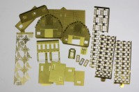
These are some of the diverse ingredients that went into the station.
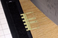
Parts to be cut are taped securely to a heavy-duty paper cutter.
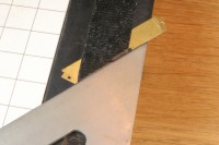
A triangle is used to ensure that angled cuts are accurate.
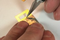
Bend points are scribed with a modeling knife held backwards.
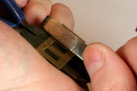
Parts are bent using flat-jaw pliers and another hard surface, such as a tool.
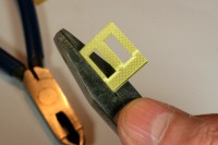
The bends are checked frequently to avoid distorting the parts.
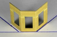
Bend angles are checked against a pattern drawn on paper.
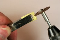
A relief cut is made to convert a window to a door.
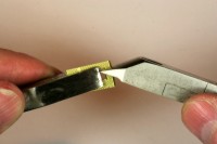
The excess material is clipped away using flush cutters.
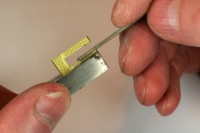
The modified opening is cleaned up with a jeweler's file.
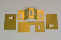
The wall parts are laid out in preparation for test-fitting .
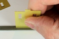
Parts are adjusted in tiny increments with jeweler's file or sandpaper.
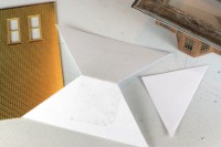
A paper mockup is made to determine the precise shapes of the roof parts.
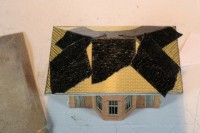
The roof parts are test-fit over and over until they're right.
Copyright © 2007-2013 by David K. Smith. All Rights Reserved.
