Matrix Control for Tortoise Switch Machines
a.k.a. "Route control for slow-motion turnout motors"
A Very Simple and Economical Design
Are you using slow-motion switch machine motors such as Tortoises on your layout? And would you like to have diode matrix-type (single selector knob) controls for your yards, the kind that modelers using solenoid machines often have? Unfortunately, the commercial products made to do this are complex and costly. But there is a surprisingly simple alternative, one that is very easy and very economical to build! Best of all, you don't have to be an electronics wizard to use it—just follow the recipe and you'll do fine.
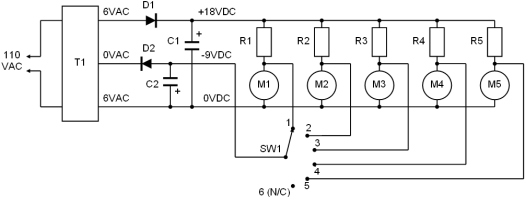
For those who know their resistors from their capacitors, the secret to the design is an asymmetrical split voltage power supply that produces a positive voltage that is double the negative voltage relative to the common terminal. Each of the switch machine motors in a matrix receives the higher positive voltage at all times via a dropping resistor, which holds the turnout in the "normal" route. A single-pole rotary selector switch then connects the lower negative voltage directly to the selected machine, thus reversing the motor direction and changing the turnout to the "diverge" route. The dropping resistor that is used to bring the high positive voltage down to the motor's normal operating range then becomes a load between the positive and negative supplies, as there would otherwise be a dead short across the power supply when the turnout is thrown.
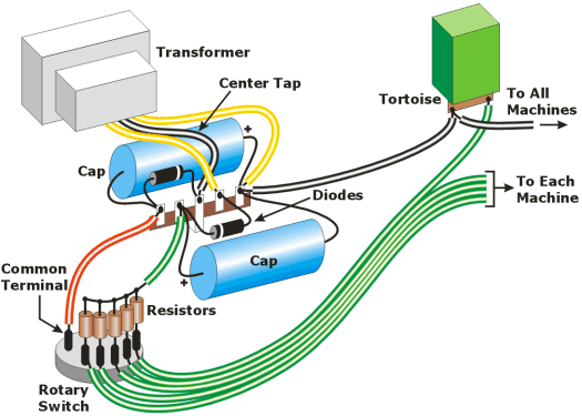
The basic circuit is shown above as a wiring diagram and below as a schematic. Essentially, the asymmetrical power supply is just a center-tap transformer—one that is normally used to create a simple half-wave plus/minus DC supply—with one of the end terminals, and not the center tap, used as common. Thus, a 6-0-6 VAC transformer will deliver +18 and –9 volts (filter capacitors raise the unfiltered voltage by approximately 50%).
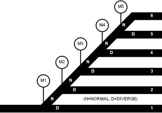
Any typical yard configuration can be controlled using this circuit. The simplest type is the straight ladder shown below. (The wiring diagrams correspond to this plan.) The normal position of each turnout sets a route through the whole ladder, and the selector switch simply reverses one turnout for the desired track. Using a 12-position rotary switch, yards of up to twelve tracks can be controlled with one knob. For the sake of simplicity, both ends of a yard may be controlled by the same circuit, assuming the yard is symmetrical and that operating practices permit.
The components specified in the Bill of Materials are selected for use with Tortoise machines, and should cost no more than about $20 total. Since Tortoise machines draw very little current, one power supply should be able to run several typical yard ladders. You can adapt the circuit for use with other motorized machines by adjusting the supply voltages and resistor ratings as necessary. The negative voltage should be in the operating range of the motor, and the positive voltage will be roughly double this. Note that motors are notorious for not always behaving as expected when using calculated resistor values, so a substitution box is invaluable in determining the appropriate dropping resistor value. When using higher-current motors, be sure all components are sufficient to handle the total maximum load.
You'll find that this system is even easier to use than its solenoid (diode matrix) counterpart: there is no button to press. Just turn the dial to the track you want, and the turnouts are immediately aligned—which means the route indicated by the knob is always the one that is actually set.
"Non-believers" (an EE actually claimed this circuit could not possibly work) should pay Rick Spano a visit and see the one I built for his Sceniced and Undecided. He'll be happy to flip open the control panel and show it off!
Other Applications
You can use this matrix control for other locations such as industrial switching areas—anywhere that several sidings branch off of a single track. Complex track arrangements just require a degree of planning; the goal is to keep the number of switch machines that are reversed at any one time to a minimum, so as to keep the load on the power supply to a minimum.
The trick to planning the circuit is to start with the route that goes through the greatest number of turnouts, and orient them all to their normal position. Select the next-most complex route, and do the same. Repeat this until all routes have been organized. The figures below show an example of a relatively complex track arrangement, along with the corresponding schematic.
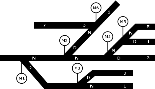
Notice that, in order to satisfy the logic needs of some complex plans, a switch machine might have to be connected to multiple selector switch contacts, and/or multiple machines might have to be connected to a single selector switch contact. Just as with solenoid matrix circuits, diodes must be used to isolate the machines from one another.
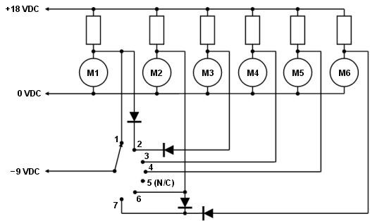
By the way, the power supply can also be used for other turnouts on your layout. As shown in the figure below, any single-pole double-throw switch (toggle or non-shorting rotary) will work. Just be sure to include a dropping resistor on the positive side of the power supply for each one.

Bill of Materials
PART |
DESCRIPTION |
T1 |
6-0-6 VAC, 1.2A center-tap transformer |
D1, D2 |
Silicon diodes, type 1N4001 |
C1, C2 |
4700 μf electrolytic capacitors |
R1 – Rn |
2.2 kΩ, 1/2-watt resistors |
SW1 |
1-pole, 6- to 12-position rotary switch |
M1 – Mn |
Tortoise switch machines or equivalent |
– |
5 lug terminal strip |
– |
Knob |
SAFETY NOTE: The power supply involves 110 VAC wiring. If you are unfamiliar with the safety requirements of 110-volt circuitry, seek the advice/assistance of a qualified electrician.
IMPORTANT: The color wiring diagram that appeared in the magazine contained an error: the wires connecting the power supply to the rotary switch were reversed (this was my fault, not Kalmbach's). The illustration shown above is correct.
