Stoplights
First Generation
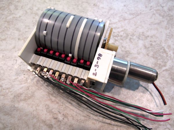
Back in 1998 I built a five-way intersection on my White River & Northern IV. The light sequence was quite complex, especially considering it included left-turn signals and pedestrian walk/don't walk signals. I found the easiest and most enjoyable way of making all of the lights operate properly was by building a player piano:
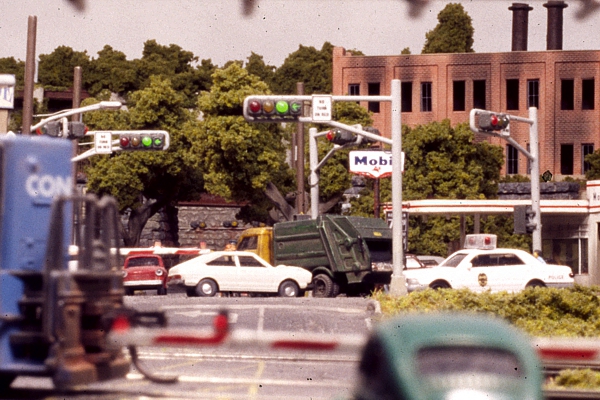
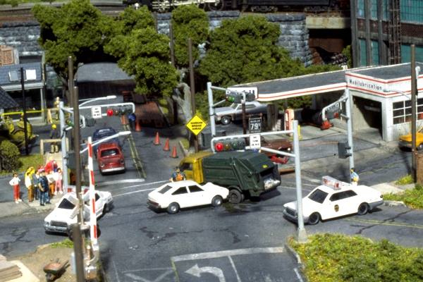
Second Generation
I regret not having any video of those lights working, but things were rather different back then. Fortunately, I recreated the stoplight effect for the Men at Work diorama, using the original player piano mechanism. The new stoplights are substantially similar to the old ones, the only difference being that now it's a conventional 4-way intersection, and not a five-way. The player piano mechanism has been "re-programmed" according to the following scheme:
The numbered columns correspond to the tracks on the drum. Oddly, this is all that's required to make the signals work properly. Each switch does not operate an individual LED, as one might expect; rather, the switches toggle between color pairs. Thus, track 1 toggles between red and track 2, and track 2 toggles between green and yellow; thus, in the diagram above, if a signal is not red or yellow, it's green—which is why there are no green bands, save for 5, the left-turn signal. The "walk" and "don't walk" signals are paired with the traffic lights: don't walk with red, flashing don't walk with yellow, and walk with green.
All of this is done for three reasons: first, it ensures that there is never more than one light on at a time for a given signal indication; second, it does away with the need for the player piano tracks to be exactly synchronized in order to create a seamless lighting sequence; and third, it uses a lot fewer switches—just five operate all 17 LEDs. Ridges on the drum for each track throw the numbered microswitches in the following schematic:
The Lights
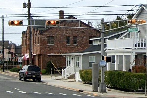
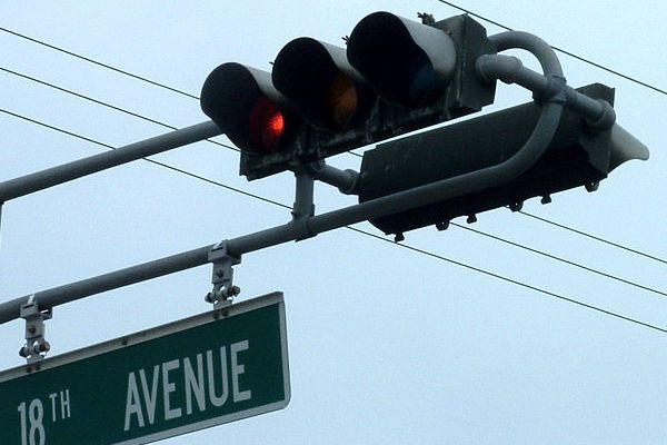
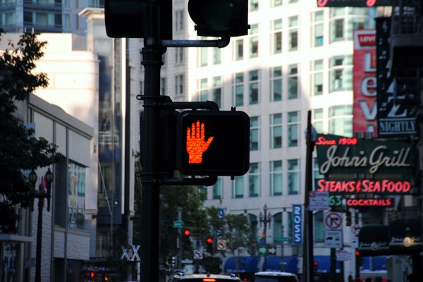
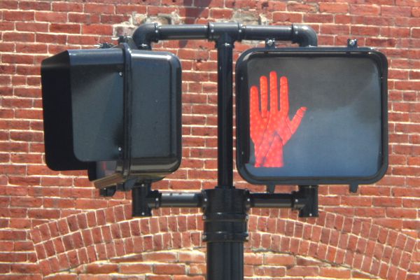
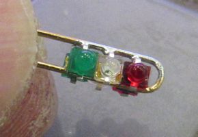
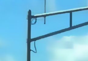
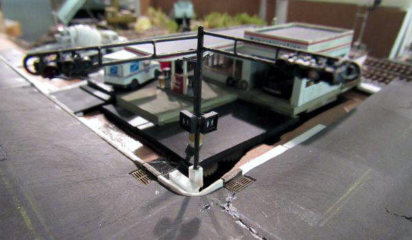
The stoplights are once again horizontal style—relatively rare, but still around. I prefer them because they're much easier to build; plus, I happen to think they look cool. As for the walk/don't walk signals, I modeled the two-part side-by-side walking figure and hand version as being the easiest to build. (The first gen had the words WALK/DON'T WALK, which were actually readable, but not something I could reproduce today.)
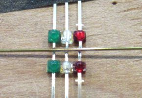
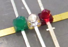
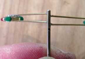
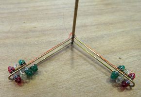
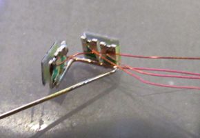
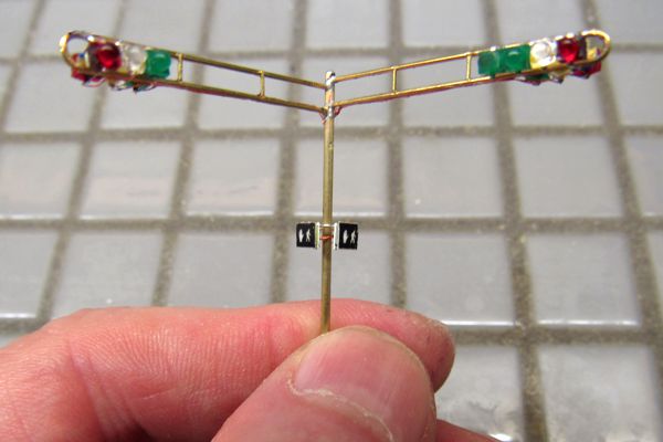
I began by making the LED assemblies. First, I bonded the 1.6mm LEDs to a thin strip of brass (above left). Next, I clipped off most of the anodes, placed two assemblies together, and soldered the anodes. Then I tinned part of a length of 0.6mm brass wire, and soldered this to the anode connections (above right). After bending the wire to shape, I bent the LEDs into position, and then clipped off their cathodes (below left), leaving tiny nubs to which I will solder fine solenoid wire.
I prepared a stanchion from fine brass thinwall tubing by drilling #72 holes for the signal arms, as well as larger holes for the wiring just below the arms and where the walk/don't walk signals go. After soldering the arms to the stanchion (above right), I wired the LEDs (below left), bonding the wires to the backs of the signal arms (below right), which was the single most tedious, time-consuming step in the entire project—indeed, I created most of this web page whilst waiting for the wires to fully bond: cyanoacrylate has this infuriating habit of either bonding instantly, or taking 5-10 minutes to fully set, the latter usually when I most need it to be quick. Incidentally, up to this point, this is exactly how I'd made the signals back in 1998.
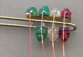
Then I threaded all of the wires down the stanchion, taking care to leave a small loop near the hole in the stanchion. I learned the hard way that the wires shouldn't be pulled taut, as it raises the possibility of shorting out on the edges of the hole. This didn't pose a cosmetic issue since, as it happens, there's a real life precedent for it (below left).
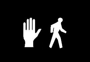
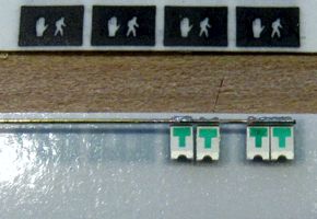
Next, I addressed the walk/don't walk signals, which is where I diverged from my originals: I found artwork online for the silhouettes (above right), which I reduced and printed on plastic label stock. The LEDs are 1206 SMDs that I simply pressed onto the back of the label stock; then I soldered a fine brass rod to all four LEDs (below left). After trimming the labels down to the size of the LEDs, I bent the rod to shape, and attached the wire leads (below right).
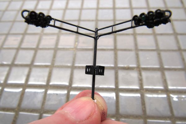
Finally, I carefully soldered this assembly to the stanchion and threaded the wires down the tubing (below left). Then I added hoods made from bits of photoetched strip brass, as well as walk/don't walk signal enclosures made from 0.010" x .060" strip styrene (below right). Before painting, I tested every LED, and determined what resistor each one needed (the primary reason I built a special tool): in order equalize the brightness, each different color required a different resistor value. I also used the testing process to fix light leaks; it took a lot of black acrylic paint to button everything up. Finally, I painted the entire signal black in order to hide all of the abundant flaws; I'd wanted to go with the more traditional yellow, but it looked awful.
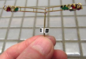
The left-turn signal, by the way, is just an LED with the dome sliced off; I painted the face black, and scribed in an arrow with a knife tip—just as I'd done twenty-odd years ago. Hey, when something works, why change it? Also, to complete the scene with the "proper" signaling, I made an additional stanchion with just the walk/don't walk lights for the facing corner. And finally, lest anyone think I just magically assemble the parts in one shot, think again. Everything was done at least twice, with loads of leftover reject parts. This is why I buy LEDs in lots of 50 or 100, instead of just 10-12 at a time. As it is, there's a total of 21 LEDs in these signals.
|
|
Reference