
Barber Pole
I have a long history making barber poles, having built three of them—which is quite a lot, considering the effort they require.
First Generation
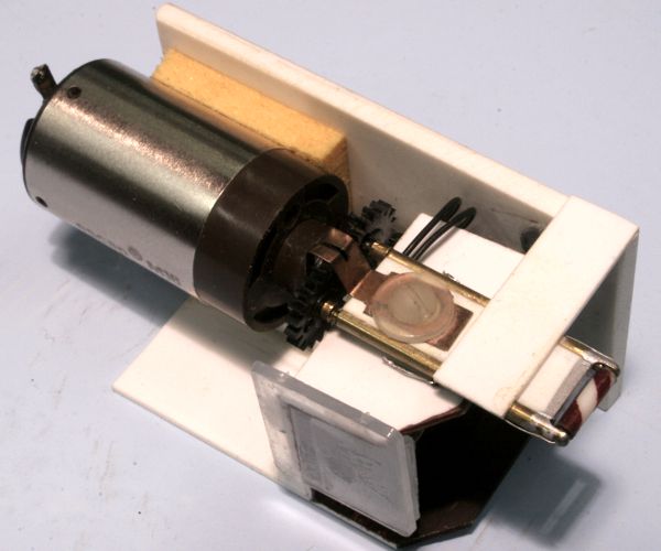
Making an animated and lighted barber pole for my White River & Northern IV was a fun challenge I'd set for myself. I also made it harder by choosing a wall-mounted pole, as opposed to one atop a stanchion, which would have been much too easy. The means of its operation is illustrated below. A low-RPM motor drives a pair of counter-rotating rods. The tapered ends of these rods engage the ends of a piece of styrene tubing, thus turning it. Inside the styrene tube is an axial lead microbulb, which is powered via the brass tubes that carry the counter-rotating rods.
The completed mechanism looks like this:
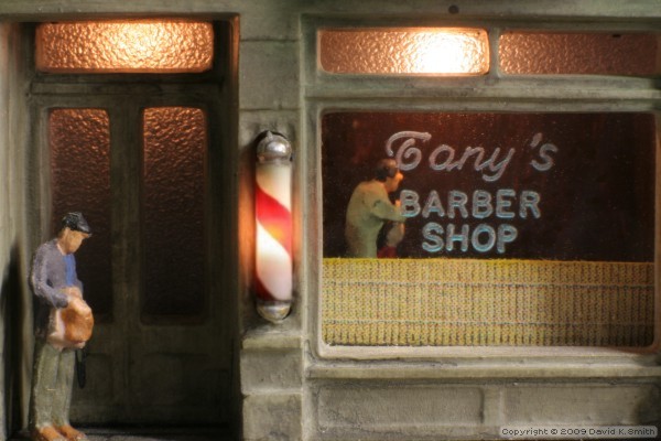
The barber shop now resides on Rick Spano's Sceniced and Undecided. The microbulb burned out 10-15 years ago, and I managed to replace it, but it wasn't a procedure I'd care to repeat.
|
|
Second Generation
For my James River Branch, my goal was to come much closer to scale than before. The first version might look impressively small, but it actually measures nearly six scale feet tall—that's a mighty big barber pole! I knew in advance that, by going significantly smaller, I'd have to forfeit illumination; even with today's nearly-microscopic SMD LEDs, there was simply no practical way to do it.
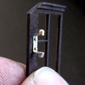
The principle behind the new mechanism is the same as the old one: a styrene pole is held in position by a pair of horizontal brass tubes, and turned by tapered, counter-rotating rods inside the tubes. The difference is that the solid styrene rod rotates inside of the brass tubes, instead of a styrene tube rotating on the outside of brass rods.
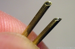
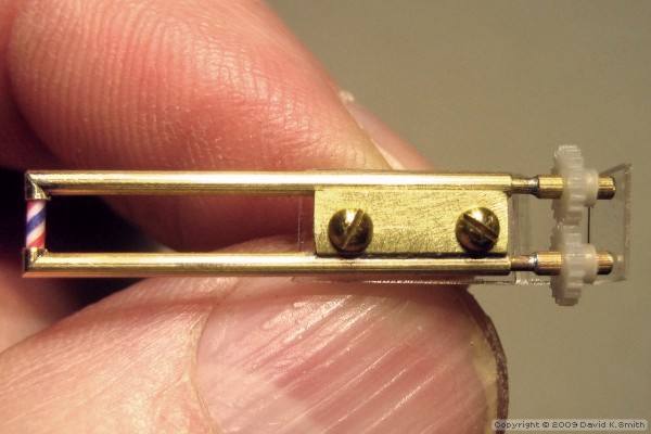
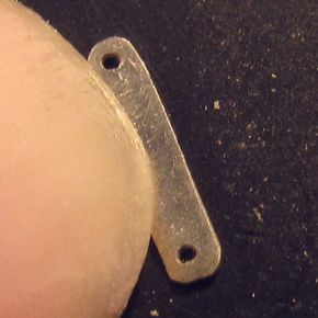
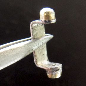
Construction began with four lengths of 0.050-inch OD thin-walled brass tube. One end of each piece was ground to a 45° angle with a Dremel tool; then the pairs were soldered together at a 90° angle to make two L-shaped parts. One leg of each part was shortened to 0.055 inches and drilled out with a #60 bit to accommodate the styrene rod. The other legs were left a full inch long so that the mechanism would not intrude on the barbershop interior, which would be visible through the window.
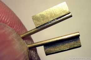
The tubes had to be held exactly parallel, so I made assembly brackets from 0.030 x 0.125-inch brass bar stock. After soldering them to the tubes, I drilled and tapped them for two 00-90 screws. Then, I cut 0.030 brass wire was cut to make two drive rods. One end of each was tapered to a point with a Dremel tool; to the other end I soldered short bits of tubing that press-fit into acetal gears.
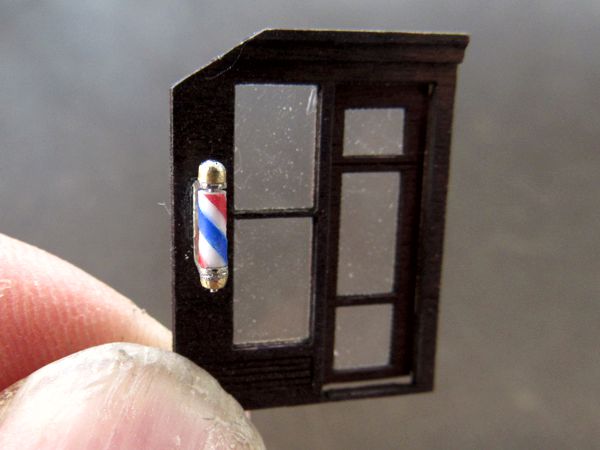
At this point I was able to determine the approximate length the barber pole itself needed to be: 0.120 inches, of which 0.100 would be visible. This happens to be a near-perfect match for a real one from the only manufacturer in the United States that still makes them, the William Marvy Company.
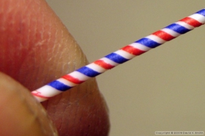
Cutting the styrene rod to exactly fit between the drive rods was an iterative trial-and-error process, because the fit had to be precise: the ends of the rod had to gently "kiss" the drive rods. Too long, an the rod would bind; too short, and the drive rods would not make reliable contact. Once I had a rod of the right length, I set it aside to serve as a pattern for one that would have red and blue stripes, because there was no way to apply the stripes to an eighth-inch long bit of styrene.
After trying about a dozen different methods, the one that finally worked best was my first idea, which had initially failed: decals. The problem was getting them to adhere reliably to the styrene rod. Curiously, I found that commercial decals didn't stick as well as DIY decal material; however, they would still come apart during the process of cutting the rod to length. Ultimately, after countless attempts to get just an eighth of an inch of decent-looking stripes, I managed to extract a useful piece intact by spraying the rod liberally with clear fixative both before and after applying the decals.
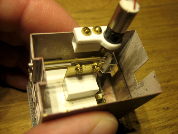
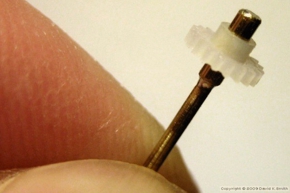
After making a gear retainer from clear plastic, I tested the operation with a geared motor, then test-fit the assembly in the building. Finally, I installed mounting blocks in the building and attached the pole assembly and geared motor to the blocks with screws. This allowed me to remove the parts as necessary, and to make fine adjustments to their position.
|
|
Third Generation
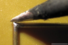
Although the second generation pole was close to scale, with the Mountain Vista Railroad I wanted to get even closer, as well as improve the cosmetics: the brass tubing at the top and bottom of Gen II was far too bulky. This meant forgoing any means of driving the pole from inside the building. Instead, I used ultra-fine wire to turn the pole directly. Although the wire is out in the open, it's barely visible since it's only 0.005" in diameter—not much thicker than human hair.
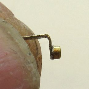
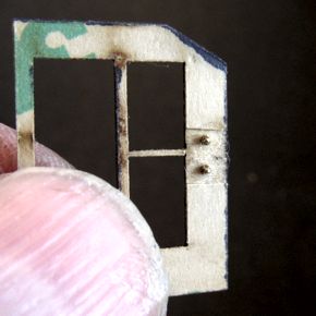
I started with the main mounting bracket. Since it's easier to shape material around holes rather than drill holes precisely within a small shape, I drilled two #76 holes in 0.010" thick plain sheet nickel, cut around it, then did the final shaping with a nail buffer. Incidentally, it took three tries to get a proper bracket.
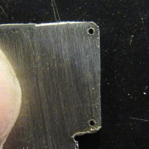
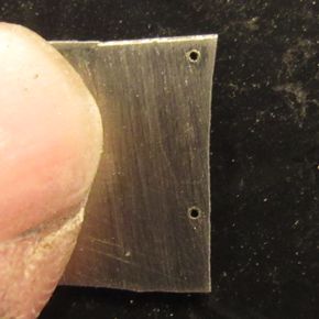
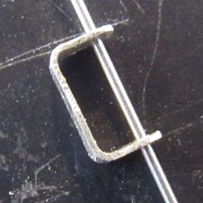
I fabricated the top and bottom caps from 1/16-inch brass tubing. First, I rounded the edges of the ends, then sliced off small sections by rolling the tube under a knife, and finally soldered the bits to the bracket. The holes filled in with solder, which was fine. The top cap needed to be filled in anyway, and the bottom one was easily drilled out for the bearing shaft.
Next, I attached the finished bracket to the structure's window trim part. I wasn't convinced that CA was strong enough for such a minuscule bonding area, so I bolted it in place with two Scale Hardware 0.5 UNM hex head bolts and nuts, threaded through #78 drill holes.
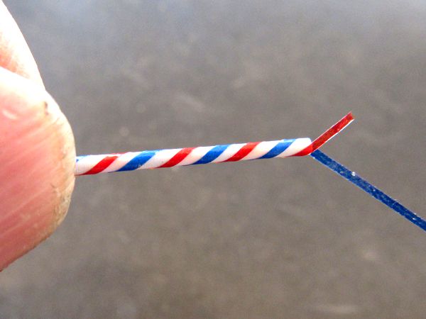
Finally, I tackled the barber pole itself. Last time, I used decals to make the red and blue stripes, but my decals had all dried up and disintegrated when I tried using them. So I cut thin strips of Scotch "magic" tape, colored them with Sharpies, and wrapped them around the pole (below), but they kept peeling off when I cut the rod to length. Finally, I applied plain tape strips to the rod and colored the rod itself with the Sharpies, then peeled the tape back off. (I lost count of how many tries this took to get right, but I think it was about a dozen.)
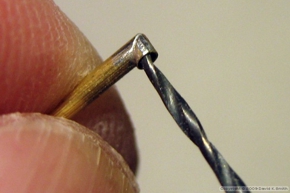
After cutting the rod to length, I drilled a #77 hole through the center to accept the bearing shaft made from a length of 0.018" stainless capillary tube. The tube is a gentle press-fit inside the styrene rod.
I mounted a length of the same capillary tube to the end of a motorized shaft, then inserted a length of 0.005" stainless steel spring wire into the tubes. Each end of the wire is crimped into a very slight W-shape to establish a grip with the tubes. A nice side benefit of this arrangement is that the whole thing can be dismantled if necessary.
|
|
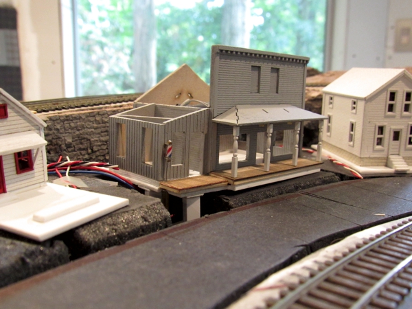
Above is a test of the mechanism; below is the permanently-installed pole.
|
|
The barber pole was relocated (briefly) to the White River & Northern X.
It now reside in the Laundromat/Barber Shop on the Men At Work diorama.