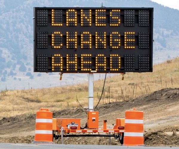
Portable Message Sign
First Build
Nearly a quarter of a century after I envisioned it, I finally saw it working...
I'd planned to make this for the White River & Northern IV but never got around to; then hoped I could build one for the Black River & Western, but that layout was abandoned.
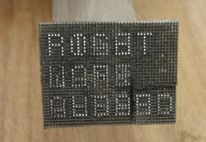
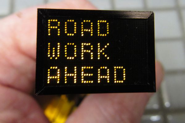
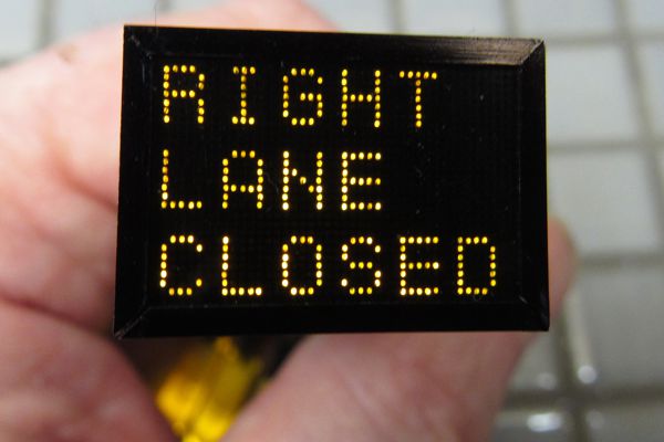
My plan from the very beginning, all those years ago, was to use fiber optics; the sign would be backed up against a tree or some shrubbery to hide the fibers. The fibers would be gathered into three bundles to produce two alternating messages, ROAD WORK AHEAD and RIGHT LANE CLOSED. With the help of a drawing program, I made a "message map," which became an all-important document going forward. First, I rendered one message in one color (below, top left) and the second message in another color (below, top right), then merged the two images together in a way that the pixels common to both became a third color (below, bottom left). Finally, I converted the colors into symbols, flipped the image (below, bottom right), and printed it.

To be sure, it was an ambitious project. I was not skimping or taking any shortcuts: the characters are full 5 x 7 dots, just as in real life. It would require over 300 fibers. Yikes! I started out using materials I had on hand. This proved futile, but it did teach me quite a lot; for starters, the concept was sound and could be made to work. It also showed me, however, that the mass of fibers exiting the back of the sign could not be disguised by a tree or some shrubs; it might require a building. Or... how about setting up the sign in front of a retaining wall for an elevated rail line? That's what's on the Men At Work diorama.
Second Build
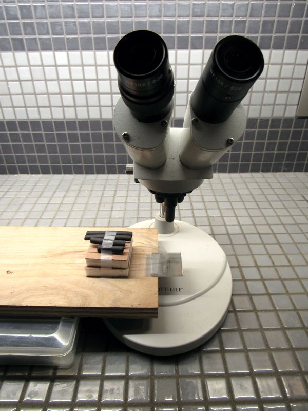
My first attempt also taught me that I needed to use better materials: I was using etched brass roofwalk for the grid (which had rectangular holes instead of square), and fibers scavenged from a fiber optic lamp (inconsistent diameter). So I started over with brand new 0.3mm etched stainless mesh and brand new prime 0.25mm fiber. But I abandoned the project owing to eye strain and making a bunch of mistakes. Months later, it occurred to me that I simply had insufficient magnification; reading glasses just didn't cut it. I had a microscope sitting around that I'd purchased for my now-disused lathe, and after an hour or so of tinkering, I had it mounted to a new stand. The microscope slashed construction time by a phenomenal amount: a project I was expecting to take at least a week started coming together in a day.
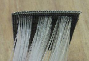
The build went like this: First, I laminated three layers of the etched mesh together so that the openings were deeper; this held the fibers more perpendicular (with only one layer of mesh, the fibers flopped around at any odd angle). Following my "message map," I inserted all of the fibers into the mesh from the back for one letter, sorted each fiber into one of three holding tubes (pieces of shrink wrap) for the different message assignments, then applied cyanoacrylate to the mesh around all of the fibers. When I'd completed all 15 letters, I clipped off most of the excess fibers from the front with flush cutters, and applied extra cyanoacrylate as "insurance." Then I took a fresh knife blade and sliced off all of the fibers flush with the front of the mesh. Afterward, I saturated the entire sign with cyanoacrylate so that the mesh layers wouldn't split apart when I trimmed the assembly to the final size with heavy-duty scissors.
That's when I was greeted with a major error: the last two letters were off by one row. I could have just built another one, but... maybe I could fix it and save myself the time and especially the expense, since I'd used up all of the raw ingredients. I sliced out the two letters with an ultra-thin Dremel cutoff disc, and repositioned them. Given the tightness of the fibers, there was no room for error, but astonishingly the gamble paid off.
Then it was time for "proofreading": lighting up the fibers to check that they all belonged in the right bundles. I found one error, but that was enough: finding a single fiber amongst hundreds is a needle-in-a-haystack task. With that out of the way, I was ready to bring it home. The next biggest challenge was finding the best way to install it, and I soon realized it would need to become incorporated into the diorama, even before I started on the cosmetic parts; indeed, I'd need to have the display installed and working, then assemble the stand—along with everything else, like the concrete retaining walls—around it.
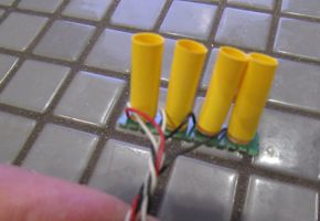
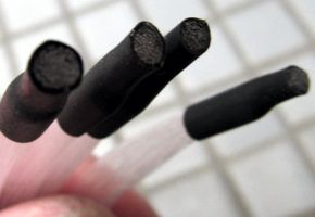
I carved out a slot in the Gatorfoam supporting the elevated line, made a styrene sleeve to fit inside it, then coupled the four bundles to the LEDs. To do this, I first fused each bundle together with CA, then clipped off the end to make a single clean interface that's held against the face of the LED with shrink wrap tubing. I mounted the LEDs on a PC board scrap that fits into a slot carved out of the back of the diorama.
The biggest challenge was doing all of the above while placing the very least amount of stress on the fibers, as they tend to snap if they're handled too much. Somehow I managed to get through it, although I did find one "pixel" that wasn't working. I've no idea if it's due to a broken fiber, or one I missed during assembly; in the end, it doesn't matter, since these old signs often had one or two lights out anyway. I'm also not especially pleased at how uneven the illumination is across all of the fibers, and I know why this is the case: the fiber-to-LED couplings could have been better. But I'm not going to change a thing; I'm just thrilled it works at all!
|
|
Third Build
Yes, the flaws of the previous build finally got to me: I knew I could do better, so I bit the bullet and ordered new mesh and fiber optic. But I was met with a speed bump right out of the gate, because the first sheet of photoetched metal mesh was defective: the front and back artwork were not in registration, resulting in an unusable product (below left). I waited long enough to get this hard-to-find item; I had to wait even longer to get one that I could use. But, true to form, the replacement was exactly like the the first; I suspect they were from the same defective batch, and no one at KA-Models bothers to QC these things. And the seller had no more. After a week of searching, I finally found another domestic seller with the mesh in stock; fingers crossed, I ordered it. (At $12 a pop, this little project has already set me back almost $50! Not to mention $30 in fiber optics...)
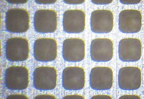

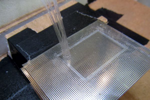
Once I finally had proper mesh (above right), I got to work. I changed several aspects of assembly. First, instead of layering three pieces of mesh together, I used two layers separated with strip styrene (below); this held the fibers more perpendicular than before. Then, I worked backwards and upside down, whereas before I just worked backwards. This solved a problem I was having with fiber curvature: before, I had to force the fibers to bend opposite of their natural curvature, which made it difficult to install as well as to fuse the fibers together for the LED couplings.
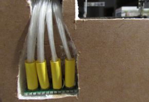
Next, rather than bond the fibers to the mesh after completing each letter, I bonded each fiber individually by applying a tiny amount of CA to the fiber itself, then slipping it down into the mesh. This greatly enhanced neatness as well as accuracy. Plus, it made the finished sign more flexible and easier to handle and install. Also, I improved the process of fusing the fibers for the LED couplings by using shrink wrap to pinch the fibers together into a neat round bundle (below left), rather than just brushing them with CA to make an irregular wad; this resulted in much more even illumination. And finally, I trimmed the mesh with a Dremel and ultra-thin cutoff disc, which avoided the tendency for the mesh to curl when cut with shears.
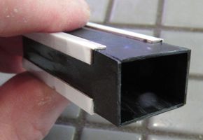
Yet another lesson learned was to build the fiber sleeve as a total enclosure that's part of the sign structure (above right). This made installation much easier and safer—the fibers were totally protected from snags and breakage. The face of the finished assembly is bright stainless (below left), and to knock this back, I placed a piece of grey tinted acetate over the display; it's held in place with the sign frame (below right).


As you can see, the previous exercise was not a waste by any stretch of the imagination; without it, I'd never have been able to make an improved model. This has allowed me to complete a longstanding bucket list item, and to see it look and work better than I'd imagined it might.
The Flasher
I'm certain some readers will be amused to learn that I built a motorized flasher. I had a very specific look in mind for the effect: first, this is a model of an older message unit, the kind that had a generator and incandescent lights, as opposed to solar panels and LEDs. So the incandescent effect was quite important. But the flashing effect I wanted was also very specific: the first message appears, then the lights dim out, with a brief pause before the next message appears; repeat. All of which is to say an ordinary alternating flasher would not work.
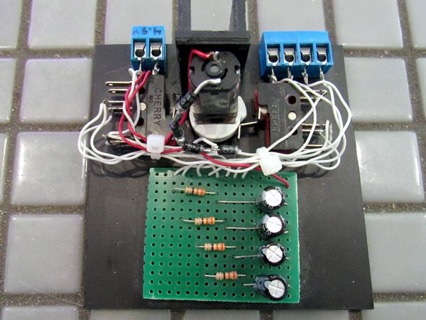
I'm sure I could have whipped up a black box to do the job, but it was much faster, much easier, much cheaper, and way more fun for me to make the motorized device. It probably looks more complicated than it really is: a low-RPM geared motor turns a cam that alternately closes one of two DPDT microswitches. There are four LEDs: one for the first message, one for the second message, and two for the lights common to both messages. The cam is shaped so there's a brief pause between the two messages, which is why the "common" circuit isn't simply powered constantly. Capacitors create the incandescent effect.
Also, there are two "common" LEDs because the common fibers created a fairly sizeable bundle; splitting it in half and using two LEDs produced more even illumination.
Reference