
The Shay, Part 6: The Crankshaft, Take 6 One may rightfully ask: how many crankshafts am I going to make? Answer: as many as it takes to get it right. The sixth might be the last, or it might be a stepping stone to an even better one. Before getting started, I studied the fifth crankshaft to see how I could refine it. I'd nailed the width of the crank assemblies, which allowed me to make the overall length of the crankshaft correct within a couple of inches. But the webs themselves were still pretty gross: the real ones are 4 by 8 inches, while the last set I made scale up to nearly double that, so anything I could do to tighten things up would help. One thought came to mind: if I was really careful with my drilling, I could maybe get the holes a little closer together. This would allow me to at least make the webs a bit shorter—although it would make soldering more difficult, as the wire rods would be practically touching. However, I'd have to live with them being too wide, because I had to leave a minimum amount of material behind for a reliable solder joint. Consider the math: a 4-inch web is only .018 inches wide, and .015 inches of that is taken up by the wire, leaving a mere .0015 inches of web around the hole! Since most or all of the difference is likely to be solder, making a scale-width web would essentially leave no metal for the joint.
Still, it was all I had, and I absolutely could not afford a precision drill press. So, was my "toy tool" up to the task? There was only one way to find out, and I had a bunch of #83 bits to spare. After a good cleaning, oiling and tweaking, the carriage was moving relatively smoothly. But things almost ended before they started when I discovered the collet would not hold the bit true. Thankfully I was able to find another collet that didn't make the bit look like a crankshaft when it spun. One last detail was that the Dremel would be too fast even on its lowest speed setting, so I hooked it up to an SRC controller to get it down to a crawl.
I only had to drill one hole in order to find out if this would work, so the experiment could have been over quickly. But to my great surprise, delight and relief, the test went extraordinarily well; indeed, it was such a success that I immediately made my little "toy" drill press a permanent resident on my workbench. (And to think that I recently had it out in a yard sale—good thing no one wanted it!)
As I began drilling a series of nearly-invisible holes in a piece of nickel silver sheet a little bigger than a postage stamp, I struggled to keep the bit from wandering around before taking hold, and that cost me two bits. The solution was obvious: make dimples first. But how to make pairs of precisely-spaced dimples? Grind two pieces of .020-inch steel wire to points, and solder them together (above left). A light tap, and presto: perfect dimple pairs (above right). And in the time it might take me to drill three or four holes by hand, I had about two dozen done, nearly all of them usable. Then, as I was cutting out the web blanks with a jeweler's saw (below left), I began to worry: was the .010-inch diameter steel wire going to hold up? It didn't seem much stronger than hair, and while it wouldn't be placed under any load when the crankshaft was finished, it could easily get mangled during one of the many fabrication steps to come. Then there were those microscopic solder joints to worry about. Once again, there was only one way to find out; I'd need to bring to bear just about everything that I'd learned up to now. Plus there were many more lessons yet to come—far too many to document here.
The next step, grinding down the web parts, was done as before by hand and in silhouette (no distracting foreground light). I've yet to find a combination of tools and techniques that allows me to be as precise as I can get by simply holding the blank in my fingers of one hand and working the Dremel tool, with a diamond cutoff disc, in the other (above right). I only need to grind them down close to their final size (below left); the last few thousands of an inch are taken off after soldering the crankpin in place to ensure that all of the part edges are perfectly parallel.
To hold the web parts exactly in position relative to one another, I threaded a pair of wires through their holes, and bonded the webs to a spacer shim with CA (above right). The wires are never quite parallel at first because the holes are not aligned precisely enough; some re-drilling is needed to get the holes in line. Then, after soldering the crankpin in place, I carefully studied the solder joints with a loupe to look for a miniscule fillet of solder all the way around the wire, within the chamfer of the hole, on the inside of the web (below left), indicating a perfect joint. The big globs of solder on the outsides of the webs would be ground off along with the excess crankpin.
Leaving the webs bonded to the spacer, I ground off the excess wire with the Dremel and reduced the webs down to their final width of about .020 inches with micro jeweler's files, fingernail files and super-fine sanding film (above right). Then I gave all of the surfaces a final finish with polishing film. You can see how the chamfer in the hole left a nice ring of silver solder around the end of the crankpin. It took the better part of a morning to do just one (not that I minded) and I still had to do it all again—twice. (Actually, I ended up doing it six times owing to any number of inevitable problems or errors.)
By the way, to give you an idea of the size of the finished crank assemblies, here's one compared to Franklin D. Roosevelt's eye.
After soldering each crank assembly to the main crankshaft (above left), I sliced the "handles" off of the webs. While the result wasn't much to look at (above right), things would improve once the cranks started getting cleaned up (below left). This was another arduous sequence of filing and sanding made particularly challenging by the fact that there was no way to hold the tiny cranks securely. As a consequence, one of them was ruined; thankfully it wasn't the one in the middle, and I was able to unsolder it, slide it off the shaft, and replace it.
But then things ground to a halt, as the next and penultimate step was to remove the excess crankshaft from between the crank webs. Up to now, this was done by simply holding the crankshaft in one hand and the Dremel—with a .009-inch thick cutoff disc—in the other. This time, however, I had zero room for error: the space between the webs was .012 inches, and taking some slight wobble into account, the cutoff disc would remove around .012 inches of material. There was no way I could ever do this holding things in my hands! It was time to make use of my new workbench resident again, except that I used it kind of "backwards." Since I couldn't rotate the Dremel so that the shaft was perpendicular to its travel, I secured the crankshaft in a hemostat, which I then clamped to the drill press carriage, then mounted the Dremel in my bench vice (above right). Although it looked like quite a kluge, it did afford good visibility of the crankshaft that I was about to possibly ruin; in spite of some nice soothing new age music playing in the background, I'm certain my blood pressure was at an unhealthy level for the next several minutes.
In the end, while it's not cosmetically as clean as number two, it doesn't have to be, for two reasons: one, when viewed by eye, nearly all of the flaws are invisible; and two, when it's installed in the crankcase along with all of the other parts, there will be much to distract from its imperfections. That said, I will be making one more. Why? Because even though I've made six already, this was the first one utilizing a number of new techniques, and so I know it can be refined; also, I could feel that one of the solder joints was a bit weak, and at this stage there's no repairing it. While the crankshaft is strong enough to be handled, I fear that its weakness may create problems down the road.
|
 Then I began to entertain
an altogether insane option, one that would actually result in an undersized crankshaft. In fact this was not such a bad thing,
since none of the crankshaft and crankpin parts are even visible in the assembled engine—they're all hidden by bearings and connecting
rods. My dubious notion was to drop from .015- to .010-inch diameter steel wire. This would mean working with sub-#80 drill bits—which
I just happened to have (down to #97). The potential roadblock here was that, in order to drill metal without breaking the super-brittle
bits, I'd need a precision drill press, and the only thing I had that even resembled a drill press was a clunky little Dremel accessory
(above right) that's anything but "precision" (I'd purchased it to do certain light-duty home improvement tasks, not
modeling).
Then I began to entertain
an altogether insane option, one that would actually result in an undersized crankshaft. In fact this was not such a bad thing,
since none of the crankshaft and crankpin parts are even visible in the assembled engine—they're all hidden by bearings and connecting
rods. My dubious notion was to drop from .015- to .010-inch diameter steel wire. This would mean working with sub-#80 drill bits—which
I just happened to have (down to #97). The potential roadblock here was that, in order to drill metal without breaking the super-brittle
bits, I'd need a precision drill press, and the only thing I had that even resembled a drill press was a clunky little Dremel accessory
(above right) that's anything but "precision" (I'd purchased it to do certain light-duty home improvement tasks, not
modeling).


 Success brought me
face-to-face with my last great challenge, one made almost impossibly difficult owing to the incredibly small size of the
parts, combined with the delicate state of the crankshaft, which up to this point was quite robust since the main shaft was all
one piece. I now had to clean up the insides of the cranks without putting any stress whatsoever on the rest of the assembly.
Ultimately what I did was modify a tool to allow me to hold the crankshaft reliably. Although my hemostat did a good job of
holding it during the previous step, it left marks on the edges of the webs. So I broke out my Dremel and modified my one and
only Hemostat to have smooth jaws. This got me halfway there; the other trick was to hold a jeweler's saw blade in my fingers
(above), which afforded much more gentle control. Following up this procedure with the tip of an X-Acto blade, I was able
to get the cranks cleaned out reasonably well.
Success brought me
face-to-face with my last great challenge, one made almost impossibly difficult owing to the incredibly small size of the
parts, combined with the delicate state of the crankshaft, which up to this point was quite robust since the main shaft was all
one piece. I now had to clean up the insides of the cranks without putting any stress whatsoever on the rest of the assembly.
Ultimately what I did was modify a tool to allow me to hold the crankshaft reliably. Although my hemostat did a good job of
holding it during the previous step, it left marks on the edges of the webs. So I broke out my Dremel and modified my one and
only Hemostat to have smooth jaws. This got me halfway there; the other trick was to hold a jeweler's saw blade in my fingers
(above), which afforded much more gentle control. Following up this procedure with the tip of an X-Acto blade, I was able
to get the cranks cleaned out reasonably well.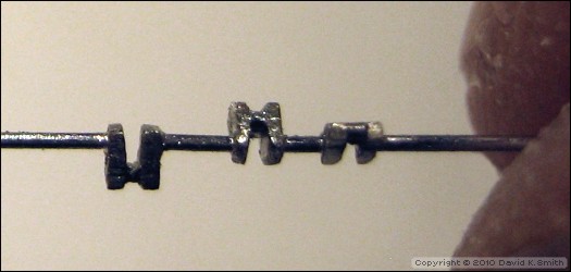

Copyright © 2010 by David K. Smith. All Rights Reserved.