
Reading MP-15DC: The Mechanism
Z scalers have been crying for an RTR switcher of most any kind since forever. I know the feeling; I've been hankering for one myself about as long. But I decided to take a different direction from the only current option, the Zthek SW-1 kit. For one thing, I wanted something with "real" trucks (the Zthek kit has rigid "fake" truck frames and only two fixed driven axles). I didn't want to make my own trucks, though, so this limited me to switchers with Blombergs.
An MP-15DC (the "DC" having been added after the MP-15AC was introduced a few years after the original MP-15) not only solved the truck problem, but thanks to its hefty proportions, it also seemed to offer the best opportunity of making a mechanism from about the only candidate for the job, the Micro-Trains GP9. Assuming I made a really snug-fitting, thin-walled brass shell, I'd just be able to keep the hood width reasonably close to reality using the Micro-Trains mechanism, which was fortunate as I needed as much metal in the frame as possible to pull this off. The truck center-to-center dimension for the MP-15DC is 24 feet, as compared to 32 feet for the GP9, meaning I'd have to slice four feet out of each end; the trick to squeezing a total of eight feet out of the frame was to "telescope" the ends into the spaces originally occupied by the flywheels.
After clipping off all of the PC board lugs with flush cutters, I cut the ends of the frame clean off at the point where the frame height drops (I used a jeweler's saw for all cutting). Next, the spaces for the flywheels were notched such that the upper sections that used to be over the flywheels remained intact; these then became the attachment points for the ends that were cut off. Once the parts were carefully filed for a snug fit, I temporarily assembled them with CA so that I could drill and tap them for 00-90 screws. I completely finished one frame half so that the parts for the other half could be adjusted to match precisely, which was achieved by iteratively assembling the parts to the completed frame half, disassembling, filing, and so on. Once both frame halves were finished, the last step was to cut away the material around the fuel tank until the trucks fit.
While the frame modification was a fairly challenging process—particularly as I have no mill, lathe or other such equipment—in terms of being stress-inducing, it was nothing compared to removing the flywheels from the motor. This task sat uneasily at the back of my mind as I worked on the frame. But ultimately it was really simple, once I decided to take a straightforward approach: I clamped each flywheel firmly in a bench vice, then gently tapped on the end of the shaft with a broken drill bit and a jeweler's hammer.
This was also my first encounter with a ceramic motor shaft, and between that and its slender size, I was at a complete loss as to how to work with it. My hope was to find some telescoping tubing that fit, but here I was faced with a "close but no banana" outcome. While I had no lathe, I did have an ordinary 3/8-inch power drill (something no self-respecting home improvement weekend warrior would be caught without). Throwing caution—and possibly a brass worm or two—to the wind, I mounted a worm in the chuck, set the drill on its lowest speed, and attempted to drill endwise into the shaft with a #69 bit in a pin vice.
Although I did waste one worm trying to get the technique down, I had spares, and so I managed to get a pair of worms drilled and press-fit onto the motor shaft. They're not perfect, but the large gear teeth are forgiving enough that it still worked. I also used the original end bearings on the worm shafts to keep the worms from wobbling under higher speeds, since the ceramic motor shaft is surprisingly flexible, and will bend slightly with relative ease.
Since I'm a DC (as opposed to DCC) guy, I had an easy job of "wiring" the motor by simply bending its contact tabs to press against the frame parts. And so in mere minutes I had the mechanism humming along nicely on a length of test track. It was time for champagne—the hardest part of the project came to a successful conclusion!
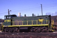
An MP-15 is a real "chunky monkey," making it an easier switcher to model.
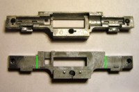
The first step is to cut each frame part into three pieces.
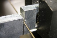
I use a jeweler's saw to make all of the cuts.
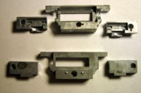
The middle parts are notched to accept the end parts.
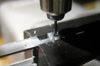
After bonding the parts together with CA, they're drilled for assembly screws.
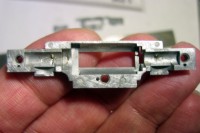
One frame half is completely finished to act as a pattern for the other half.
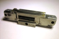
Parts for the second half of the frame are filed to mate with the first half.
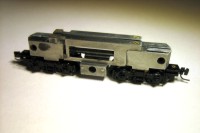
The fuel tank area is cut back to clear the trucks, and everything is test-fit.
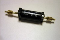
The worms are drilled end-wise using an ordinary power drill and a pin vice.
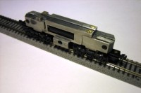
The assembled mechanism undergoes a power test.
Copyright © 2007-2013 by David K. Smith. All Rights Reserved.