
Plate Girder Deck Bridge, Part 1 of 2: The Bridge
In the real world, the overall dimensions of the girders in plate girder bridges are always proportional to the length of the bridge, which means an N scale plate girder is perfectly fine to use in Z. Really! The only thing wrong, if you want to get picky, is that the rivets and other details will be slightly oversized. But this minor discrepancy is very easy to live with, as far as I'm concerned.
Thus, Micro Engineering makes a couple of nice Z scale plate girder bridge kits, and hardly anyone knows it—including Micro Engineering. Their N scale 40-foot deck and through bridges become 55-foot Z scale bridges. Since girder depth can vary a little according to the load the bridge is designed to carry, it's perfectly fine to lop off one or two panels to make slightly beefier 40- or 48-foot girders.
Also, Atlas makes a useful one-piece N scale 65-foot through plate girder bridge. Since it has no inside-surface detail, it doesn't make a very good through bridge, but it works fine as a deck. With one panel cut off, it makes an 80-foot Z scale deck bridge.
The James River Branch required two bridges: a high trestle and a short through bridge. The trestle in these photos actually has quite a bit of history behind it. I had originally planned to use a Micron Art Pratt through truss to span the river valley on the previous version of the layout. But after assembling the kit and placing it in position, it became obvious that it would not work. That was an expensive lesson to learn, especially considering that the alternative was so economical.
The Pratt truss was replaced by a series of four deck spans: three plate girders and a truss. When I abandoned that layout, I kept the bridge to reuse, which led to a curious little good news/bad news situation: the bridge needed to be shorter, so the bad news was that I had to eliminate the truss span; the good news was that I had to eliminate the truss span—it was an embarrassing bash job that I was quite happy to throw out.
The current bridge comprises six Micro Engineering 40-foot N scale deck plate girders cut down to 48 Z scale feet (one panel was removed from each part). They were finished off with Evergreen .020 x .080 strip styrene parts on the bottoms and ends, then connected end to end.
There was no practical way to see into the space between the girders after the bridge was assembled and installed, so I didn't worry about making realistic internal cross bracing; I also wanted the bridge to be reasonably sturdy. So, the two bridge sides were joined with fifteen .030 sheet styrene squares. I bonded them all to one side of the bridge, then attached the other side.
The areas that were somewhat visible—the top and bottom of the bridge—received proper cross-bracing, which was made from .010 x .040 strip styrene bonded to the spacer blocks. Then, .020 bearing plates were added to the bottom of each end of each girder to complete the bridge.
Painting started with two base coats of Rustoleum Ultra-Flat Black. Over this I made a series of light, irregular alternating sprays of Rustoleum Ruddy Primer and Ultra-Flat Black, and then finished with several heavy Rustall washes.
Since all visible track is handlaid, ties had to be bonded to the bridge before installation. I use Fast Tracks Z scale PC board ties, which come pre-cut to 17 feet long, and I simply cut them in half.
I made a jig to arrange the ties for the bridge. A brass bar was secured to a work surface with masking tape. Then a strip of double-stick tape was attached to the work surface along the brass bar. After exposing the adhesive, I placed the first tie on the tape against a small square so that the tie was perpendicular to the brass bar.
Using a piece of .030 square brass strip as a spacer, I continued placing ties on the adhesive strip. Every once in a while I would use the square to be sure the ties were still running perpendicular to the brass bar. I left the bridge sitting nearby so I would know when I was done placing ties.
After I had enough ties down, I pressed down on them firmly to make sure they were secured to the tape. I cleaned and evened their surfaces with an abrasive block. Then, I applied a bead of thick CA to the top edge of the deck plates, positioned the bridge over the ties, and held it tightly in place until the CA was set.
Rubber cement thinner helped to release the ties from the double-stick tape. I trimmed the uneven ends of the ties with a flush cutter, then sanded both ends of the ties, as well as their tops, with fine sandpaper.
Piers and abutments were fabricated from Pre-Size cast resin N scale cut stone wall material and sheet styrene. The piers were bonded to the bridge before installing it on the layout—it's easier to make the scenery meet the piers than to make the piers meet the bridge.
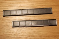
Micro Engineering N scale deck plate girders are shortened and detailed.
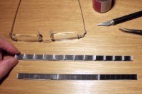
After attaching spacer blocks, the two halves are joined and braces are added.
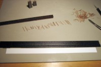
A tie assembly jig is made from a brass bar and double-stick tape.
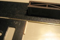
The first tie is positioned on the double-stick tape using a square.
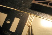
A thin strip of brass is used to separate the ties as they are added.
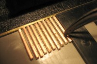
The ties are checked periodically to be sure they are aligned.
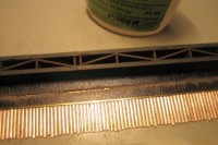
After positioning all of the ties, they are cleaned with an abrasive block.
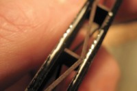
A bead of thick CA is applied to the top edge of the deck plates.
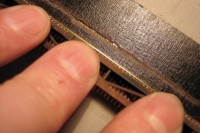
The deck plate assembly is held tightly against the ties until the CA is set.
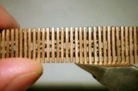
The uneven ends of the ties are trimmed with a flush cutter.
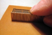
After trimming, the tie ends on both sides are sanded.
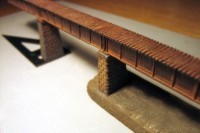
The piers are attached to the bridge before installation on the layout.
Copyright © 2007-2013 by David K. Smith. All Rights Reserved.