
Working With Micro-Trains Switches
Working with Micro-Trains roadbed switches can be a source of frustration for beginners. But this can be avoided by being aware of a few simple rules. Once you've got these tips committed to memory, then things will go much more smoothly.
Here are the key points to remember about Micro-Track switches:
- The track part attached to the straight route must be notched.
- A special joiner is used on the notched side of the notched track.
It's relatively rare that a track plan will feature Micro-Track switches in their "factory" configuration—that is, with the pre-notched straight track (provided with the switch) connected to the straight route. Therefore, you'll need to be prepared to do a teeny bit of surgery on whatever piece of track is connected to the straight route.
Don't worry, it's really quite easy to do if you follow the rules. You'll only need two things: a fine marking pen, and either a sharp knife, diagonal wire cutters, or a pair of heavy-duty scissors or shears. You can even use a file or sandpaper, but this is messy and takes time. The ideal tool is a pair of flush cutters, which results in a quick, clean cut.
Before we start cutting up track, though, let's look at the special track joiner and the role it plays. When two adjacent pieces of track are connected to a switch, the ends of the roadbed must overlap. Since this isn't possible, one piece is notched. The piece that isn't notched is so close to one of the track joiners that the joiner needs a recess to clear it.
The first photo at right shows two track joiners: the special one, top, and a normal one, bottom. You can see the recesses in the special joiner that clear the adjoining track roadbed.
The second photo is an underside view of track assembled to a switch. The special joiner is colored purple. You can see how the recesses in the special joiner clear the corner of the upper track roadbed.
It's important to pay attention to the special joiner! It's easy to lose track of it because of which track it's connected to on new switch sets: for left switches, it comes connected to the switch itself (Photo 3), whereas it's connected to the notched straight track for right switches (Photo 4).
This is probably the first source of frustration for beginners—and even some veterans—when working with switches: if you aren't paying attention to the placement of the special track joiner, the track will be difficult to assemble to the switch.
Now that you're an expert on the special track joiner, we can talk about notching track. Remember, the notched piece is always the one connected to the straight route; the track connected to the diverging (curved) route does not need to be modified.
The first thing to do is mark the track to be notched. This is best done by using the factory-notched track as a guide. Place the pre-notched track on top of the piece to be notched, and mark the roadbed with a line that follows the same slope. Note that the notch begins between the first and second tie on the very corner of the roadbed, and it ends between tie 6 and 7, as shown in Photo 5.
If the track to be notched is connected to a right switch, you'll need to remove the plastic track joiner. Then you can notch the track using whatever cutting tool you have on hand—in Photo 6, I'm using a pair of diagonal cutters. Photo 7 shows the result of the surgery.
If the notched track is being attached to a right-hand switch, you'll need to remove the special joiner from the factory-supplied straight track, and connect it to your newly-modified track. Be sure the recesses on the special joiner face the edge of the track, and not the center.
Photo 8 shows the result of the procedure. The track pieces should connect easily, with no need to force anything, and with all joints aligned and tight.
One last important point about joining track—and this applies to all track joints, not just switches: be sure the rails are properly joined. Roadbed track has two joiners per rail: the plastic roadbed joiner, and the metal rail joiner. Unfortunately, it's all too easy for the rails to be misaligned, and when viewed from above these misalignments are hard to spot. So, be sure to inspect each track joint carefully to avoid the situation shown in the last photo.
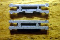
1. The special track joiner is compared to a regular track joiner.
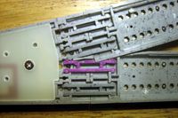
2. The special track joiner (highlighted) is shown in position from below.
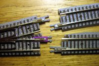
3. The special joiner comes attached to the switch for left switches.
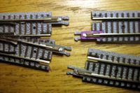
4. The special joiner comes attached to the notched track for right switches.
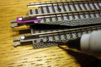
5. Mark the track to be notched using a pre-notched part as a guide.
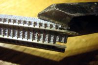
6. Cut the notch with diagonal cutters, a sharp knife, or a pair of shears.
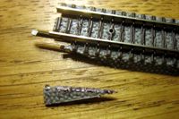
7. The finished notch should look just like this one.
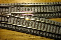
8. The newly-notched track mates with the switch perfectly.
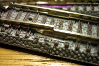
9. Be sure to avoid misaligned rails!
That's it! When the procedure is all spelled out in detail, it may seem just a little intimidating. However, it really boils down to a less-than-one-minute procedure. The important part is to remember the special track joiners; this will make your life much easier, and your modeling much more enjoyable!
Also see:
- Bury Those Bulky Switch Machines!
- Cutting Micro-Trains Roadbed Track
- Measuring Curved Track for Cutting
Copyright © 2007-2013 by David K. Smith. All Rights Reserved.