
Bury Those Bulky Switch Machines!
The switch machines for Micro-Trains switches (Photo 1) are too bulky to fit in many track configurations. The design was probably a function of practicality: a smaller machine—or, ideally, an internal one—would likely have made the switches prohibitively expensive (although Rokuhan has presented us with something of a breakthrough). Consequently, it makes many track plans impossible to build with remote controls. What can you do?
You can bury the switch machine! As it happens, it's relatively easy to mount the switch machine directly to the underside of the switch. Doing so means cutting a hole in the roadbed to accommodate it, of course, and providing access from under the layout is recommended. But it's not an onerous task for moderately experienced modelers.
The whole modification process can be accomplished in about a half hour—15 minutes once you've done a few. Here are the tools you'll need:
- sharp knife
- #0 Phillips head jeweler's screwdriver
- 2mm slot head jeweler's screwdriver
- small needle-nose pliers
- tweezers
- pin vice
- #54 drill bit
- 3/16" drill bit
- fine marking pen
- ruler
There are two new parts required for each switch (Photo 2). One is a very tiny screw, which is available from Eishindo. They're made for laying T Gauge flex track, and come in a pack of 100 for about $6.50 (check this page for sources). The other part is a small piece of Evergreen 3/16-inch styrene tubing.
As an aside, I keep the screws in a small beading storage jar, available from craft stores such as Michael's. I also cut pieces of styrene tubing in advance and keep them in a beading jar as well. This way they're all stored safely and ready for me when I go to work on a switch.
Step 1. Dismantle the switch by removing the four screws from the base plate on the underside of the switch (Photo 3). Do not remove the fifth screw, located centermost, as it holds the points in place. When the base plate is removed, the switch machine is released from the switch. Carefully set all of the parts aside.
Step 2. Dismantle the switch machine. Using a slot head jeweler's screwdriver, gently pry the retaining clips until the catches release. This is best accomplished beginning with the clip on the closed end, then working around the side (Photo 4). Once you've got around half of them loosened—there are six of them—you should be able to remove the lid. This takes patience and practice to master. Finally, extract all of the internal parts.
Step 3. Modify the bottom part of the switch machine shell. First, clip off off the mounting tabs with a sharp knife. Then, at the center of the long open edge, measure and mark a rectangular area 1/16" by 1/2" as shown in Photo 5, and cut it out with a sharp knife.
Step 4. Modify the plastic slider. First, clip off the small manual operation nub with a knife. Then enlarge the rectangular hole next to where the nib was removed, creating a roughly semi-circular recess, as shown in Photo 6.
Step 5. Mark the switch base plate for the position of the switch machine. Using a ruler, draw a 3/8" by 2" rectangle exactly centered around the square opening in the middle; see Photo 7. Position the switch machine bottom shell part over the rectangle such that the beveled side faces the curved side of the base plate and, while holding them tightly together, flip them over and mark the two screw holes on the switch machine shell bottom; see Photo 8.
Step 6. Drill the switch machine shell bottom with a #54 bit at the two marked spots. Then countersink the holes from the inside of the shell using a 3/16" drill bit (I just spin the bit in my fingers). The countersink should be as deep as practical; see Photo 9.
Step 7. Carefully remove the main slider bar from the switch. Make a mark at the midpoint of the magnet and centered along the bar, as shown in Photo 10. Drill a #54 hole at the mark, then countersink the hole from below; the countersink should be as deep as practical.
Step 8. Cut a 1/8" long piece of styrene tubing by rolling the tube under a knife—this helps ensure the ends are square. Holding the tube in a pair of needle-nose pliers, attach it to the main slider bar using the track fixing screw. When the screw is snug, check to be sure its head is flush with the surface of the slider bar; see Photo 11.
Step 9. Reassemble the switch. Before securing the base plate, be certain the slider bar engages the spring part at one end and the electrical contact at the other. Replace the two endmost screws first, then check to be sure the mechanism works properly. Next, position the switch machine bottom over the two inner holes, and thread the two screws through the switch machine bottom and into the switch (Photo 12). Important: Do not over-tighten these two screws, as this can cause the mechanism to bind or—worse—the threads to strip.
Step 10. Reassemble the switch machine. Be sure the solenoids are properly seated, then insert the plastic slider such that it properly engages both the solenoid plunger and the newly-installed pin on the switch. When all of the parts are positioned, replace the switch machine lid. Be sure all of the retaining clips are engaged; see Photo 13.
This completes the modification. The only other thing to do is test the switch for proper operation. The most likely causes of failure include 1) over-tightened assembly screws; 2) misaligned solenoids; 3) improperly installed main slider bar; 4) screw holding the styrene tube in place is not fully flush with the slider bar.
As you can see in Photo 14, the machine is completely invisible. If for any reason you wish to undo the modification, the switch can be restored to its original configuration by dismantling and removing the switch machine, detaching the styrene tube, and reassembling everything the way it was. The only thing that would be different is the nub used to operate the machine manually will be missing.
Also see:
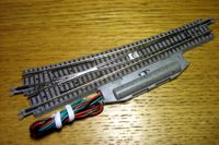
1. The MT switch machine is bulky and severely limits track planning options.
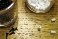
2. The only new parts required include a tiny screw and piece of styrene tubing.
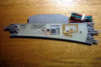
3. The switch is dismantled by removing the four base plate screws.
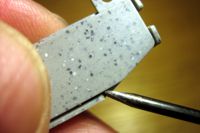
4. The switch machine lid is removed by prying the retaining clips free.
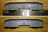
5. The switch machine shell bottom is marked and a piece is cut out.
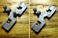
6. The small plastic slider from the switch machine is modified.
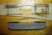
7. The switch base plate is marked to position the switch machine shell.
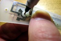
8. The switch machine shell is marked for two holes to drill.
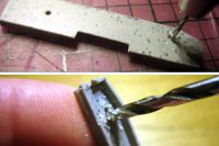
9. Holes are drilled in the switch machine shell and are countersunk.
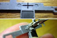
10. The main slider bar is marked for a hole to be drilled and countersunk.
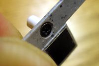
11. The styrene tube part is attached to the main slider bar with the screw.
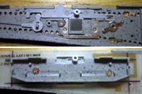
12. The switch is reassembled along with the modified switch machine shell.
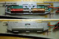
13. The switch machine is reassembled on the switch base plate.
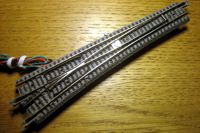
14. The completed modification results in a totally invisible switch machine!
Copyright © 2007-2013 by David K. Smith. All Rights Reserved.