Stephen A. Greene & Sons Building Supply, Part 6 of 6: A Light Over a Door in a Dark Corner
In the photo at right, Jim Greene is seen at the back door of the Stepehen A. Greene Building Supply office, as he often is at any random time of day. But as evening approaches, this corner of the building gets altogether too dark for his liking. So one day he made arrangements to have a light installed over the door. It was easy for him: just tell a hired hand to do the job. Since I'm the hired hand, that meant I'd be working at 1:220.
Inspiration for this detail came about when I purchased a bunch of white 0402 SMD LEDs from Kingbright USA. These things are smaller than fleas—without a doubt the smallest electronic components I've ever had to work with, and probably right at the very limit of my ability. How small are they? The LED type indicates their dimensions in thousandths of an inch, so they're .040 x .020 inches.
To help readers visualize these dimensions, I asked Jim's niece, Wanda, a waitress at Dot's Diner, to pose with an 0402 SMD LED. (Bear in mind that she's a Z scale person—which isn't meant to be discriminating in any way; it's just a fact of life.) As you can see, the LED is about the size of a Z scale toaster. And a Z scale toaster is the kind of object one must be in a particularly good mood to manipulate; if one's the slightest bit irritable, it's best to move on to something substantially larger—say, a mountain.
I've also found that it's helpful to work in the middle of a clean, blank sheet of white paper; this makes it somewhat harder to lose the toaster, although I can attest to the fact that it's no guarantee—twice as I was turning an LED over with a tweezers, it leaped just like a flea off of the paper and onto the floor. Amazingly, I was able to find it both times.
Before I got started, I had a mental picture of how this might come together. I'd start with .010-inch brass wire for the neck of the lamp, bent into the traditional "P" shape. I'd solder the wire to one terminal of the LED; then I'd run a bit of ultra-fine (#42) solenoid wire along the back side of the brass wire to the other LED terminal. For a shade, I have some Ngineering N scale 12-inch/Z scale 18-inch aluminum lampshades (#N7008-8).
It was time to see if my plan would work. Bend brass wire: check. Solder brass wire to LED: check. Solder solenoid wire to LED: check. Bond solenoid wire to brass wire: check. Test LED: check... and boy is this little sucker bright! It's going to need an extra dropping resistor for sure; otherwise, it will look like a Z scale toaster going supernova. It will also need a transparent orange paint treatment to warm it up, because it's also way too blue (the photo at right is a reasonably accurate rendition of the actual color).
To address the color temperature problem, I simply dipped the LED in Tamiya Clear Orange paint, and allowed it to dry an hour or so. (This also served to insulate the LED terminals from the metal shade to come.) It took two applications to get the blue under control. Meanwhile, I drilled an Ngineering shade with a #76 bit. This was easier to do than I'd expected, because the shade is more robust than it looks—I could grip it with tweezers just tightly enough for drilling without causing damage. Although a #80 hole would have easily fit over the wire, it wouldn't allow the shade to make it around the tight gooseneck over the LED.
With the color temperature corrected, I slipped the shade into place and secured it with CA. Then I applied gloss white paint to the inside surface of the shade as well as the whole LED, since it was visible below the shade, and the white paint gave it a vaguely lamp-like appearance; in addition, it toned down the brightness to just the right level—it wouldn't need an extra dropping resistor after all. I also made an escutcheon from .035-inch styrene rod: I drilled the end of the rod stock with a #80 bit, then cut off a ~.010-inch slice and bonded in place. Finally, I painted the fixture with Floquil Weathered Black.
To install the light on the building, I drilled a hole in the wall just above the door. Then I bonded a scrap of PC board, with the copper split in half, to the ceiling of the second floor. First I threaded the solenoid wire through the wall, followed by the brass wire, and soldered them to the pads on the PC board. In order to allow the building to be removed from the layout, the PC board has a pair of screws to which the supply wires are connected.
I'm happy to report that Jim is very pleased with the job. However, I'm not so sure he'll be pleased to learn that I've started dating Wanda...
Postscript: Owing to the fact that the building has been completely redesigned, the light has been relocated. It made no difference to Jim; he's delighted that his business has now doubled in size.
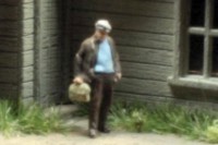
Jim says this shadowy corner is in need of some extra light.

Wanda holds up an 0402 SMD LED to give us an idea of how small it is.

The neck of the fixture is made from .010-inch brass wire bent to shape.

The end of the brass wire is soldered to one terminal of the LED.

Solenoid wire is soldered to the other terminal of the LED.

The solenoid wire is bonded to the side of the brass wire with CA.

Before adding the shade, the LED is tested: it's bright! And it's blue, too.

After tinting the LED with clear orange paint, the shade is bonded in place.

This styrene escutcheon is one of the smallest parts I've ever fabricated.

Wanda shows off the finished light, which is now ready to install.

The light is soldered to a terminal block mounted inside the building.

Now the corner is nicely lit, and Jim can see where he's going.
![]()
![]()
![]()
![]()
Copyright © 2007-2013 by David K. Smith. All Rights Reserved.