Crossing Flasher, Part 2 of 2: Flashers
As complicated as the cantilever assembly might appear to be, it was the easiest part of the entire project by a wide margin. I knew in advance that making the lights work would be a challenge, but turned out to be far more difficult than I'd imagined, involving a painful, protracted process of trial and error which I've documented in my blog. Here I'll just cover the highlights of those techniques that actually worked.
After assembling a target from the TrainCat #0300901 Type "D" Mast Signals kit, I was a bit disappointed. It didn't look like a flasher target: the hood was too small and not shaped right. So, the next hour was spent rummaging through just about every drawer, box and bag in my workshop looking for inspiration—which ultimately arrived in the form of .060-in. OD thin-walled brass tubing.
To make the hood, I first ground away half of the tube with a diamond cutting disk in a Dremel tool. After cleaning up the edges with an X-Acto blade, I shaped the end of the tube with 320-grit carbide sanding film. But how to cut the finished hood off of the tube without sending it flying off to Iceland? I cut most of the way through the tube with the Dremel, leaving just enough "connective tissue" intact to keep the hood in place; then I simply broke the hood off by gently flexing it back and forth with a tweezers.
After sanding the cut edge of the finished hood, I dipped it in a drop of CA and positioned it on the target while the target was still on the fret, which permitted precise positioning over the slot provided for mounting the original hood. Then I cut the target free from the fret and cleaned up the edges. After priming the fronts of the targets, I painted them flat black. Then, using a toothpick, I applied a tiny drop of Tamiya clear red paint into the hole in each target to make lenses.
Random modeling tip: To hold tiny parts securely for painting, attach them to the sticky area on the back of a Post-It Note. The adhesive is just strong enough to hold the parts in place, but allows them to be removed easily without damaging the finish.
While the targets were drying, it was time to start working with type 0603 SMD LEDs (the type number indicates dimensions: .060 x .030 inches) and #43 solenoid wire (which is ~.002 inches in diameter—about the size of human hair—and so delicate it can be broken by a cat fart). Fortunately I'd already gained some experience working with these bitty things from lighting the barn.
I've learned that it helps to bond the LEDs with CA to a piece of smooth stainless steel (I use a ruler); this holds the LEDs securely during soldering, but they're easily removed by popping them off with a knife. After tinning the tip of a piece of solenoid wire, I'd position it on an LED terminal pad and touch it briefly with a soldering iron. It only takes a fraction of a second to make the joint; any longer, and the LED breaks free and remains stuck to the iron, and before it can possibly be removed, it's toast. Once all of the wires were attached, I tested the LEDs.
To make the brackets, I drilled a #65 hole in some .030 x .060 strip styrene, and two more #78 holes at right angles to the first hole to accommodate .015-in. brass wires. After trimming the part down to size, I split it in half so that it could be attached to the stanchion. I inserted .015 brass wires into the two small holes and bent the wires to shape. Next came lamp housings, which I made from thin slices of 3/32-inch styrene tubing. I drilled #78 holes endwise in the slices, then bonded them to the wires on the brackets. Finally, I trimmed the wires and sanded them flush with the housings.
The wired LEDs were bonded to the backs of the lamp housings. After painting the housings, the brackets were bonded to the stanchion. The common anode wire was soldered to the cantilever (this step alone gave me a few grey hairs); the two other wires were strung along the back of the lower cantilever arm and bonded in place with CA. Then they were threaded into a hole drilled in the main stanchion below the cantilever, fed down and out the bottom, and soldered to the plug. Finally, the targets were bonded to the lamp housings.
The very last item to fabricate was the crossbuck: I downloaded artwork, printed it at maximum resolution on coated paper, and laminated it to heavy-duty aluminum foil. After touching up the paint and weathering it, I temporarily wired it to the flasher circuit and captured the effect on video, as seen below. Seeing it flashing made all of the pain and aggravation of building it worthwhile!
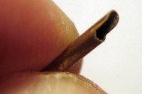
A hood starts with a shape ground into the end of thin-walled brass tube.
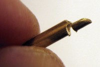
After cutting most of the way through the tube, the hood is snapped off.
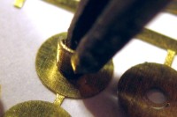
The hood is bonded to the target with CA while the target is still on the fret.
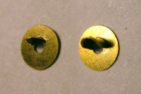
The original kit target (left) is compared with the modified target (right).
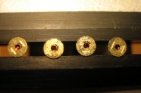
Lenses are made by applying tiny drops of transparent red paint in the holes.
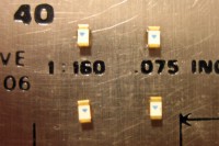
LEDs are bonded to a stainless steel ruler with CA for wiring.
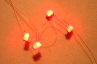
After the wires are attached, the LEDs are removed from the ruler and tested.
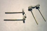
Brackets are bits of strip styrene and brass wire, with styrene tube housings.
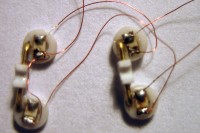
LEDs are attached to the backs of the lamp housings.
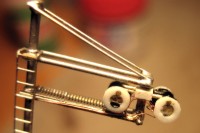
The brackets and lamp housings are attached to the cantilever.
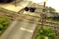
The completed flasher is detailed, weathered and installed.
|
|
Copyright © 2007-2013 by David K. Smith. All Rights Reserved.
