
Rising To the Occasion
For my entry on breaking ground, some construction details were a tad ambiguous. But the reason for this is completely innocuous: I was simply so excited by the swift layout progress that I raced through the end of the post, skipping a raft of images and information. So, here's all of the missing stuff on how I created the subroadbed grades using only Gatorfoam and carpenter's glue.
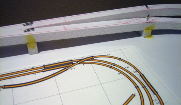
Long before saw met foam, I'd worked out the elevations and grades in AnyRail, my track planning software of choice. The first step was to set and lock the heights for key locations: the track at zero level, the switch for the branchline, and the end of the branchline. After a few rounds of slope smoothing and corrections, the software then told me what I needed to know: the grades (ranging between 3.4% and 3.6%, as shown below) and, more importantly, the elevation at each track joint.
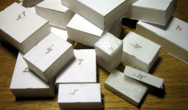
The heights at the track joints were the starting point to derive "idealized" elevations in quarter-inch increments. I placed these numbers manually on the track plan, and then printed the plan so that I had a guide from which to work (below).
Previously I described how I'd made the Gatorfoam risers: they were all cut from a long strip of leftover material with razor saw and a miter box for precision.
Before setting the risers in place, however, I had one critical section of subroadbed that required a different approach: the switch for the branchline. Because this was a relatively long stretch that had to be dead flat, I made a large, solid riser cut to the length of the section, then added a shorter part to make an "L" shape (oriented on its side) for stability. This was glued together and weighted down for a few hours to thoroughly set.
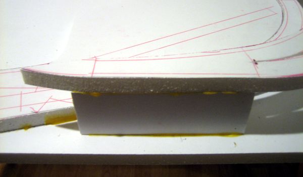
Using my printed guide, I then glued all of the risers in place, and pinned them with large T-pins to secure them until the glue set.
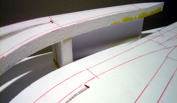
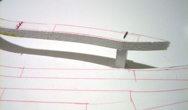
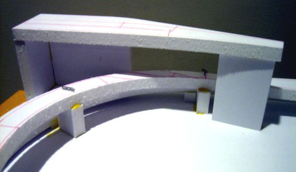
One riser, however, was not glued: the last riser on the stone viaduct. Because this stretch of subroadbed might be removed altogether, I simply left the riser pinned in place until I reach the point of building the viaduct. (Incidentally, you can see where I changed my mind about where to cut the subroadbed. I was originally going to end it at the beginning of the viaduct, then thought better of it; having no idea how I'll be building the viaduct, I felt there might be an advantage to having the subroadbed in place.)
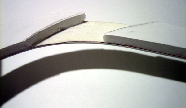
One oddball piece of subroadbed was the portion of the branchline between the plate girder bridge and the wooden trestle. This was a separate piece that required some "special attention": because of close clearances, it had to be notched on the underside. This would weaken the Gatorfoam considerably, so before notching it, I laminated a piece of .080-inch thick sheet styrene on the top surface (and adjusted the risers to compensate).
The last piece of subroadbed to install was the end of the branchline. Because it's located at the end of the wooden trestle, it's essentially a separate, standalone section. The subroadbed part is supported on three large solid panels to hold it perfectly level.
At the end of the day, this is how the layout looked:
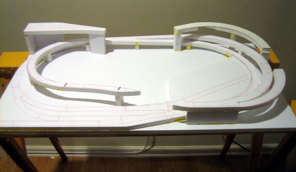
It's quite a thrill to see the layout come so far so quickly. I'm sure there will be speed bumps with which to deal on the road ahead—there's already been some adjustments necessary because of the close clearances by the plate girder bridge—but overall so far it's been a pretty smooth ride.