
5. Everything Is Under Control
Plan A
One thing I had no intention of doing was using an old-fashioned power pack—not when I have an abundant supply of super-cheap, excellent PWM throttles (originally made as LED dimmers but ideal as small motor speed controls). As for the control panel, I'd originally wanted to build it into the layout fascia, but with so many turnouts and uncouplers to operate, that became impractical. Now it will be a separate box with a roughly 8 x 10 inch panel.
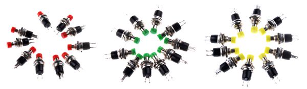
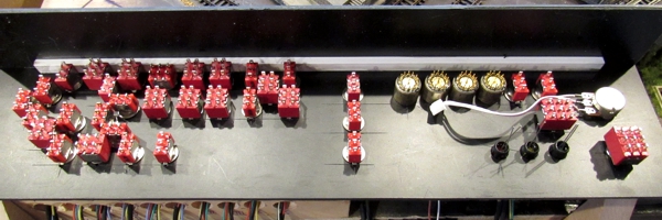
The panel will be populated with pushbuttons that were readily available from Radio Shack back in the day, and now sold for pennies apiece from Hong Kong and Chinese suppliers (below). Red and green buttons throw the turnouts, and yellow ones activate uncouplers. The grey circles are on-off switches to kill track power in select areas so multiple locos can be run, albeit one at a time (no A/B cab system), plus a pushbutton for the rolling lift bridge.
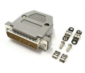
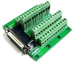
The panel will be connected to the layout via a DB44HD plug and socket set (above), and the panel box will contain the power supply: a bank of AA batteries. This way the layout can be run anywhere, without the need for an AC outlet. While this is a relatively modern arrangement, it was an option in the 60s or 70s, albeit a more expensive one at the time.
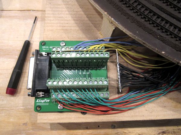
By Independence Day of 2019, I had the layout completely wired up to the point of the DB44HD socket (above). The much-less-fun part (the cable) is yet to come. Note the large bus bar: the layout utilizes a common return for everything, including track power, turnouts, uncouplers, etcetera.
Plan B
After rebooting the project, I decided not to go with the separate panel, and instead have it built into the layout. Most of this had to do with being a little lazy: I didn't want to deal with making a cable and wiring it to a separate box. A secondary reason is that, with the addition of working signals, crossing flashers, street lights and building illumination, there weren't enough circuits in the DB44HD to carry it all. So I decided to make the panel a permanent fixture on the layout itself; thus all of the above is no more. The downside is that I'd have to completely rewire the layout; the upside is it's still less work than making the cable for a separate panel and fabricating the panel and box.
The new panel would need to be smaller to fit the available space, so I was just going to arrange the controls in rows, numbered to key with the turnouts and uncouplers; however, I really prefer a graphic diagram. I got it to fit by using subminiature momentary-contact center-off toggles instead of pairs of pushbuttons to control the turnouts. This allowed the panel to be more compact, with fewer holes to drill and fewer connections to solder.
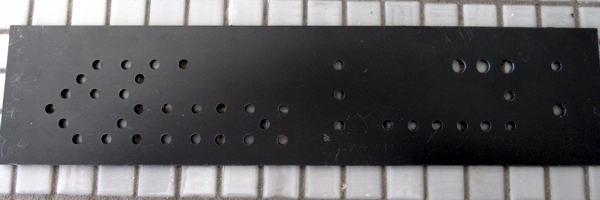
I made the panel the same way I've been making them since the mid-1990s. After determining the final size of the panel, I cut it out of ⅛-inch thick black sheet styrene. I printed the artwork on plain paper, taped it to the panel, and made dimples with a center punch for all of the controls and indicators.
Then I drilled out all of the holes.
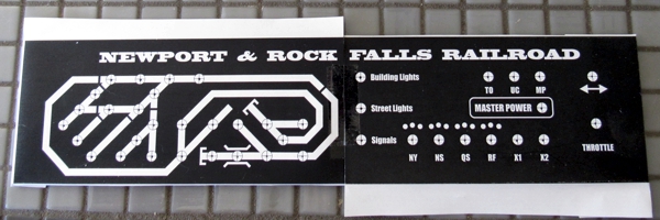
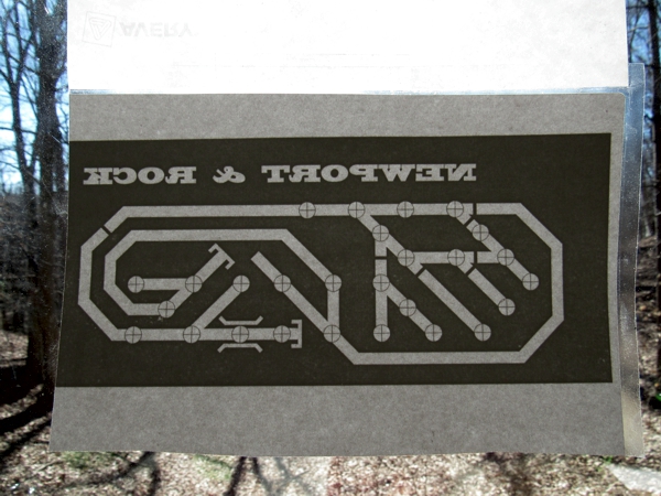
After printing the panel artwork on self-adhesive label stock and laminating it with clear film, I taped it to a window to let Mr. Sun show me how to align it on the panel.
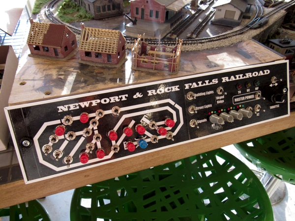
Once I trimmed the label stock and opened up all of the drill holes, I was ready to start installing the controls. (The signal indicators, lower right, were simply colored with Sharpies.)
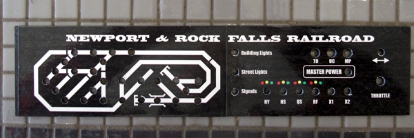
That's one packed panel!
I was ready for the arduous task of wiring this little beastie...
Wiring reached the 98% mark on 14 March 2021. (The small green PC board just to the right of center is the throttle.)
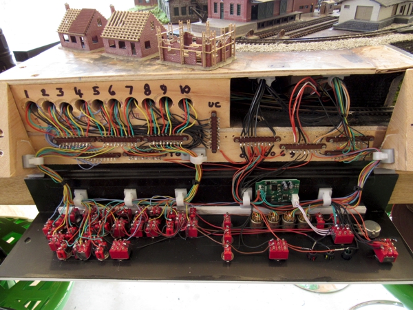
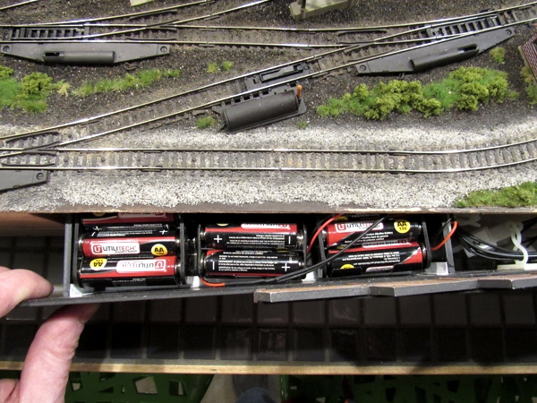
On that same day, I installed the battery holder in the same panel that holds the background buildings.
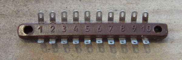
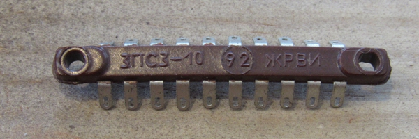
Incidentally, those nifty miniature terminal strips seen behind the control panel were made in—and purchased from—Russia. I can easily envision Sputnik bristling with them.
Revisions
On 26 March 2021 it became clear that I had to do a minor redesign of the right half of the control panel to accommodate five new lighting controls. I un-mounted all of the switches, peeled off the old artwork, applied the new artwork, drilled new holes as needed, and reassembled everything.
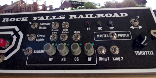
Compare the image above with the right half of the one below.
Power Supply
As I've been doing with all of my recent portable layouts, I've gone with battery power. This layout is a little unusual in that it has "old fashioned" twin-coil switch machines as well as uncouplers, which require a bit more juice. The layout has three identical 9-volt AA-cell battery packs:
- one pack for the throttle (it also serves as a supply for the lift bridge)
- one pack tied together with the above pack to provide switch machines and uncouplers with 18 volts
- separate pack for lighting
I kept the throttle/accessories separate from the lighting so that the lights aren't affected by the operation of the train or accessories. Also, a capacitive discharge unit fires the switch machines so they throw more reliably.
Acid Test
15 March 2021 was a landmark day: a full test of the control panel and the entire electrical system. It was just a bit unnerving simply because I wired absolutely everything (including dozens of controls and hundreds of connections) all at once. Lucky for me, everything was nearly 100%. The only issues were:
- a pair of swapped uncouplers
- two switch machines wired backwards
- one switch machine was DOA
Once I've straightened up the rat's next of wires inside the tunnel, I'll be able to run trains!