4. With a Little Help
As I'd learned some years back, I've lost some of my fine motor skills, making it difficult to hand-lay track. But for a little backwoods railroad, Code 40 track was a must. So I took advantage of the kind assistance of an exceptionally skilled modeler who offered to hand-lay Code 40 turnouts for me. They truly are works of art.
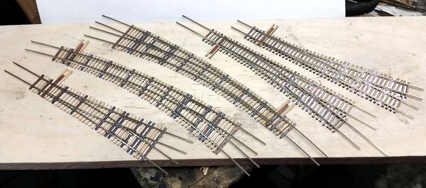
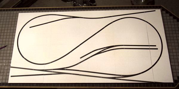
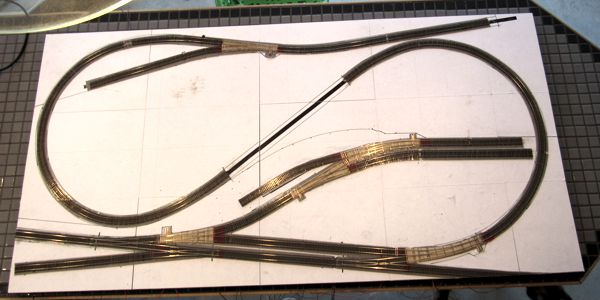
Once I had the turnouts in hand, I got busy laying out all of the track on a full-size print of the plan (below).
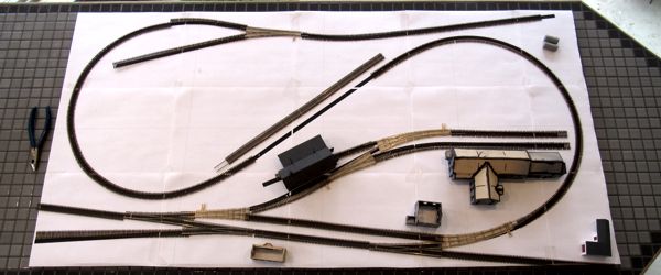
Satisfied with how things should work, I made the necessary adjustments to the plan, printed it on 8.5 x 11 plain self-adhesive label stock, trimmed the edges with a paper cutter, and applied the labels to a sheet of half-inch Gatorfoam (below). I placed the turnouts in position once more so I could mark where the throw rods had to go.
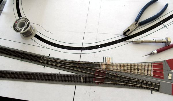
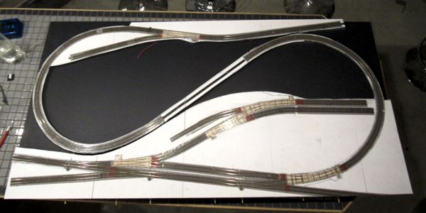
Because I'll be operating the turnouts manually with direct linkage, I had to start laying track on the roadbed sheet of Gatorfoam before it got cut out and installed on the base (below). I laid the track using 3M VHB double-sided tape; each length of track got electrical feeders soldered to the undersides of the rails.

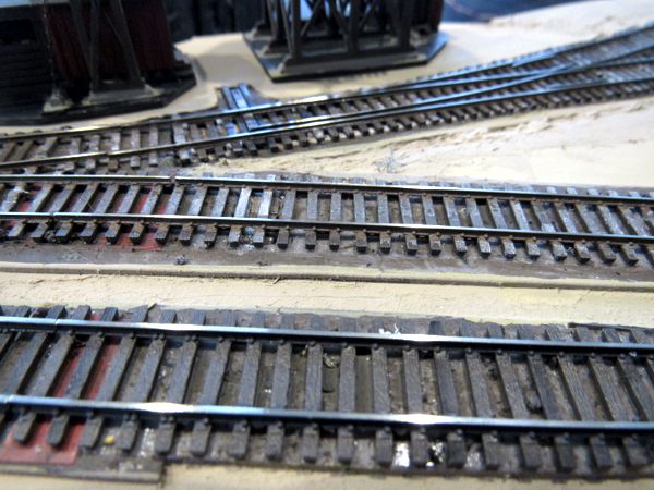
The nail-biting was over in a few hours after I completed two of three Code 40-to-55 transitions and got my first custom Code 40 turnout installed. (The two bright squares at the lower far right comprise a homemade magnetic uncoupler.)
Soon I had the third 40-to-55 transition done and my second Code 40 turnout installed. Then the following day (22 March 2020) I had all of the track laid, save for the trestle.
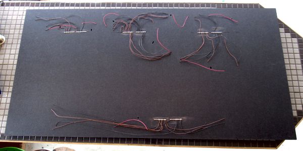
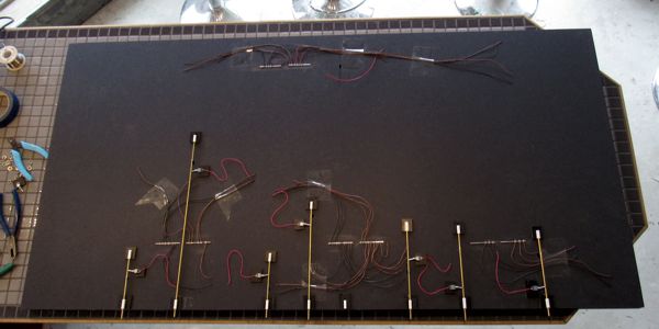
Wiring couldn't have been any easier: the layout is a DC system all on a single block. After installing a bunch of terminal strips, I finished the wiring in a half hour (below).
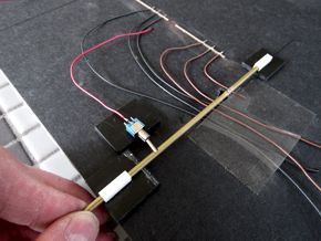
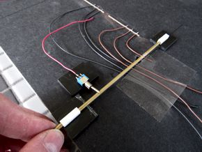
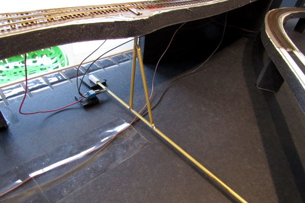
Turnout controls comprise a brass tube to which a piece of spring steel wire is soldered; the wire protrudes up through the layout base and into a hole in the throwbar. The brass tube is held in place on the base with a pair of guides made from square styrene stock bonded to mounting plates. Finally, a micro-miniature SPDT toggle switch mounted to the base engages a slot ground in the side of the brass tube to hold it in one position or the other, and also route power to the frog. Eventually I'll attach some sort of knob to the end of the brass tube.
Next, I cut out the roadbed layer cookie-cutter style with an X-Acto knife. Note that I left the section of roadbed where the trestle goes intact (dead center, below); this will ensure that the slope is perfectly matched at both ends. Once all of the roadbed is secured to the base, I'll remove that section.
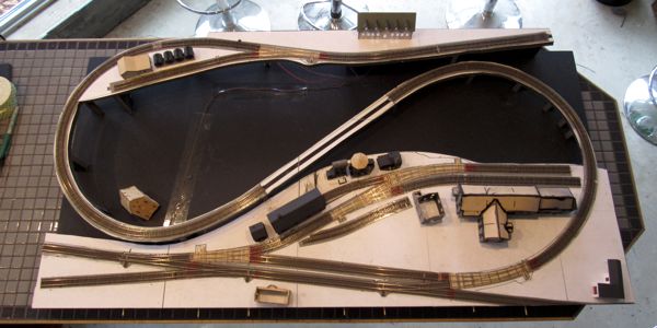
After cutting Gatorfoam "risers," I glued the roadbed to the base. Below, I've posed a number of structures on the layout to get a sense of how they fit in their 3D setting.
Then I built the "special" control linkage for the last turnout at the back of the layout. And with that, on 23 March 2020, the base and trackwork were all done.
On 13 April 2020 I painted all of the track.