
Excavator
First Generation
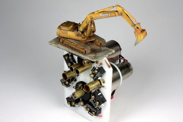
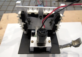
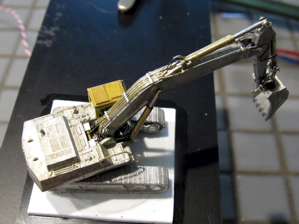
Created for the White River & Northern IV, the excavator was one of the most popular animations I've done; people from all around the world were contacting me about it when I first posted the videos back in the early 2000s (some of them were denying it was real). It was the single most challenging animation project I'd ever attempted. Based on a heavily-modified GHQ kit, it features four degrees of motion. The actions are driven with low-RPM geared motors that move the parts though monofilament line. Except for cab rotation, all of the movements are created by gear drives with limit switches.
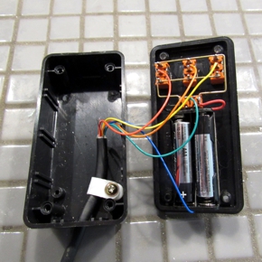
The controller also contains the power supply:
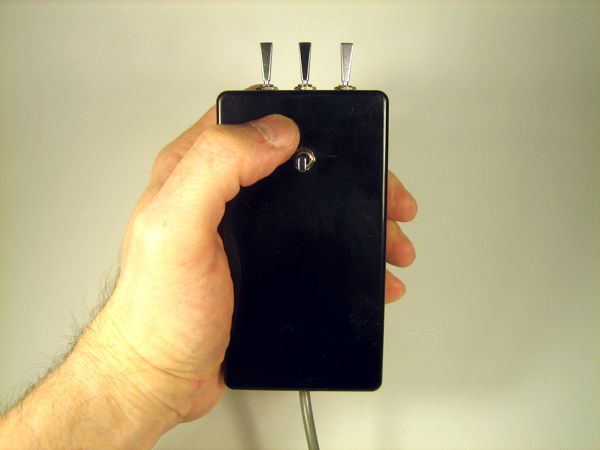
To keep the number of wires between the controller and the excavator to a minimum, I used a positive/negative power supply, comprised of two battery packs in series, with the common between them.
The device's operation is a bit complex, and is best understood through the following videos:
|
|
|
|
Regrettably it started suffering from "arthritis" (not unlike its builder), and I was unable to come up with a treatment plan that worked. Ultimately it ceased functioning altogether, and since it wasn't built to be repaired, it was decommissioned.
Second Generation
Recently I was inspired to try again, just for the sake of tackling a big challenge (and subsequently it inspired the Men at Work diorama). At the time of writing, I had no plan for the diorama or what else might join the excavator, although a dump truck would be a good bet, positioned near the dig site to create an endless loop for the material. At any rate, the advantage I had going into the project was knowing the mistakes I made the first time, so this new one should be better.
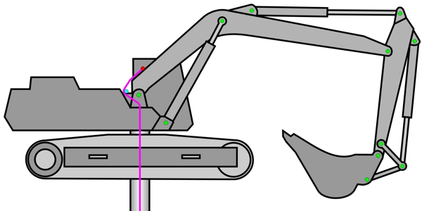
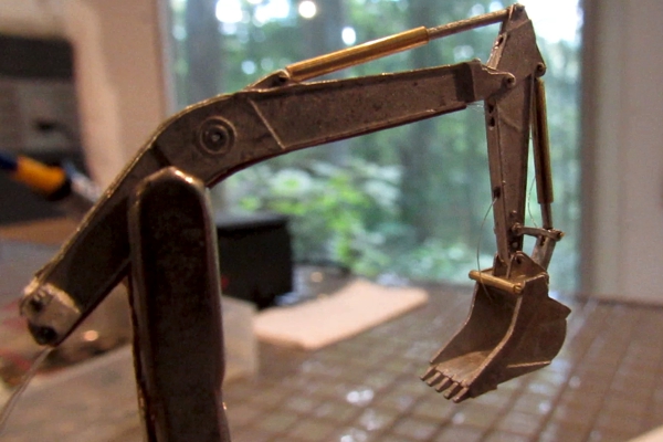
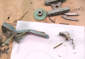
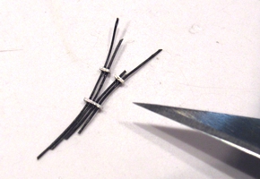
First, I'll go over how the excavator functions. The green dots are pivot points; red dots are thread anchor points; blue dots are fulcrums added to increase leverage; pink lines are the monofilament threads that actuate the moving parts. This is the thread arrangement for the bucket:
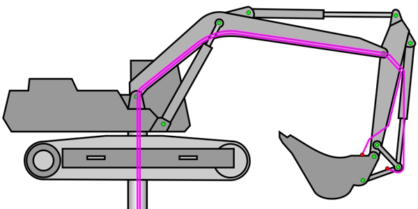
The thread arrangement for the upper boom:
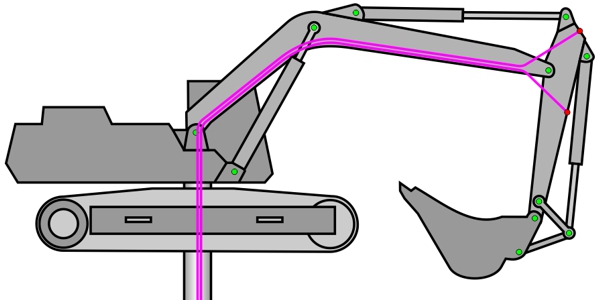
The main boom thread arrangement differs in that there is only one thread to raise it; gravity lowers it:
DAY 1. The project got going better than I'd expected; the first and hardest of the articulations—the bucket—was assembled and working by the end of the first day.
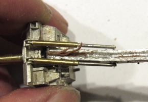
Creating the pivots involved drilling a total of 16 #80 holes (reamed out to around #76) just for the upper boom and bucket assembly; the pivots were completed using 0.015" brass wire with the ends crimped to lock them in place, just as I'd done the first time.
|
|
DAY 2. I joined the upper boom and main boom, and then ran the actuating threads. It took some tinkering to get it working right, but in the end I nailed it. One difference I made this time was to use a length of wire insulation for a thread guide along the underside of the main boom, instead of just covering a slot with sheet metal. Although the new method lacked cosmetic appeal, it offered the advantage of smoother, more reliable operation because now the threads moved within a smooth, clean enclosure, and for me, functionality trumped appearance.
|
|
DAY 3. I was off to a good start: I made a base plate for the cab, ran all of the threads down through it, and installed the main boom. This paved the way for work to begin on the mechanism.
Over the course of days 1 and 2, I thought about the changes I'd make to the original mechanism. For starters, the geared motors I chose came with magnetic clutches, so instead of limit switches, I'd use hard stops; this would simplify construction and wiring. Also, instead of anchoring both threads for each function together on the winding drum, I'd wrap only one thread around the drum, and attach the other thread to a spring. This would compensate for the fact that the travel for the two threads isn't always the same, and tying them together on the drum caused occasional periods of tension and slack on some of the threads; it would also provide some "give" in case the mechanism jammed or the operator did something wrong.
But as I got into the mechanism's construction, right away I was met with problems. The most disappointing was the clutch magnets: they were so strong that they interacted with one another, forcing them all off-kilter. So it was back to limit switches, which I had to cram into an already compact mechanism—the new motors were much smaller than the old ones, so everything got tighter. It also meant redesigning the thread drums, since there was no practical way to use the clutch parts, which had nice built-in drums. Just to pile it on, even the cab rotation worm drive was giving me grief. So Day 3 was very close to a complete bust. At least I had a pretty good idea what I had to do the next day.
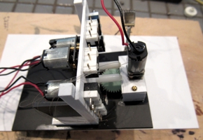
DAY 4. I made up for about half of the progress lost the day before. This time I managed to get the mechanism assembled, but only got the cab rotation working after switching from a worm drive to spur gears. I needed a break from the excavator, so I built the controller (see below).
|
|
A New More Compact Controller
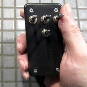
Electrically this unit is identical to is predecessor (scroll up for the schematic), except that the motors run on 1.5V instead of 3V, so I dug up the smallest electrical box I had, a two-cell AAA battery holder, and four bat-handle SPDT MOM-OFF-MOM (momentary contact center off) toggles. Everything fit perfectly. I completed this in a couple of hours.
DAY 5. In my rush to get the mechanism started, I skipped past completing the two pistons for the main boom, so I got them out of the way first thing. Then it was on to the most challenging aspect of the project: creating the mechanical components that drive the movements. First, I had to determine the total travel of the threads for each articulation, then convert travel (t) into winding drum diameter (d) having a maximum of 180° of rotation (3d = 2t), fabricate winding drums, and finally divine some means to anchor the threads.
A great many variables contribute to the challenge, such as thread stretch, uneven thread travel, winding drum wobble, and a host of others, but anchoring the threads is the biggest of them. It was a serious issue the first time: I tied them off at wire posts inserted into the winding drums, which was a nightmare because tying knots at precise locations on monofilament thread is virtually impossible. I needed a new strategy.
Quite often when I hit a creative wall, I'll stop modeling and start writing—putting things into words can help create a different perspective. As it happens, a fair bit of this website was created while trying to work through problems. The solution I came away with, after mentally trying on a half-dozen or so, was to wrap the thread around the winding drum several times, then tie it down to the miniature equivalent of a boat cleat mounted atop the winding drum and secure it with CA (knowing full well that CA can't bond nylon, but hoping that multiple wraps around the cleat would provide a sufficient foothold for the CA).
As it happens, it went as planned. The only glitch was that the threads stretched a little, and the travel became offset. Unfortunately there was no un-anchoring the thread without potentially damaging it, so I spent a couple of hours scratching my head over the problem. My solution was to install an additional thread guide post to take up the slack. And with that, the excavator was functionally half done.
|
|
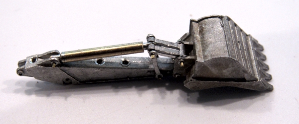
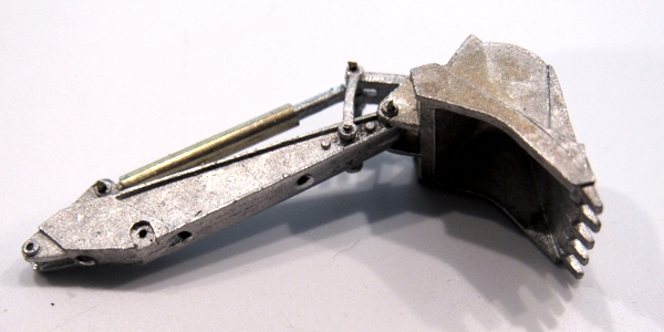
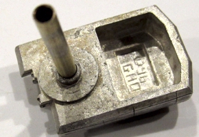
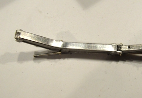
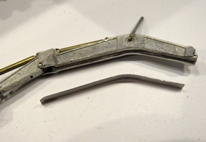
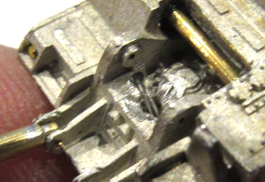
DAY 6. It was time to tackle the toughest part of the motorization process: connecting the upper boom and bucket to their respective drives. What made it so challenging was that the two threads for each part had to be perfectly balanced and indexed on the winding drum. I vividly recall the grey hairs I acquired during this process the first time. Things started out really well: I had the bucket working far better than it had the first time. But things quickly unraveled when I attempted to get the upper boom working. It was quite impossible, and the reason was soon clear: the threads for the bucket exited the upper boom too far away from the fulcrum, which locked it in the lowered position. I tried a couple of fixes, including a spring-loaded tensioner for the bucket threads, but when all of the bandaids failed, it was clear there was only one solution that would work properly: replace the upper boom with one having the thread holes drilled were they belonged. It's an awfully good thing I thought to buy two kits!
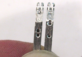
So, the rest of Day 6 was spent extracting the excavator from the base, dismantling and replacing the upper boom, rethreading it, and reinstalling it. In the photo above right, the original part is on the left, and the replacement is on the right; note the location of the middle thread hole.
DAY 7. Getting back to where I was 24 hours before took less time than I anticipated, given the number of steps I had to retrace. But with each pair of steps forward, it seems there was always a step back. This day brought something new, unexpected, and highly undesirable: the upper arm moved, and with a full range of motion, but it jittered, not unlike the hands of its builder. The bucket was even worse, exhibiting fits of spasms. But wait, it worked fine during the bench test on Day 2; what was different? That was an excellent question for which I had no answer. It had me vexed to the point I considered abandoning the project. But I'd come too far to throw in the towel, so I resigned myself to dismantling it again.
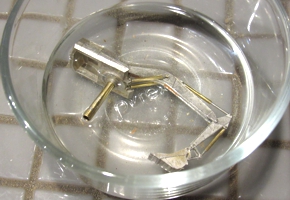
I determined the problem was the thread guide on the bottom of the main boom—the very thing that was supposed to improve performance. For whatever reason, the material (wire insulation) was "sticky" to nylon thread. I figured it would just peel out of the channel in the boom, but no; the bond was super-good. Fortunately there's nothing mechanical on the model that is secured with CA, so I placed the whole thing in an acetone bath. Unfortunately, I didn't have a spare boom; this was the spare, so I had to make do. On the prior model, I simply covered the channel with a strip of thin sheet brass, which I really didn't like, but the thing of it is, it worked. Unable to find a suitable replacement thread guide substitute, I reverted back to Plan A.
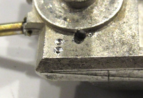
Plan A worked out for the better when I found some etched stainless steel fret exactly the width of the boom, so that was a big cosmetic win that saved me a lot of work. Then I decided, while I still had the thing apart, to add a little detail I'd wanted to include ever since I found some excellent reference images. That little indentation at the corner of the cab houses a work light, so I dug out my prewired warm white 0402 SMD LEDs, and started drilling holes.
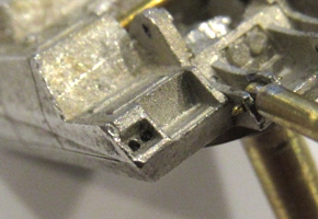
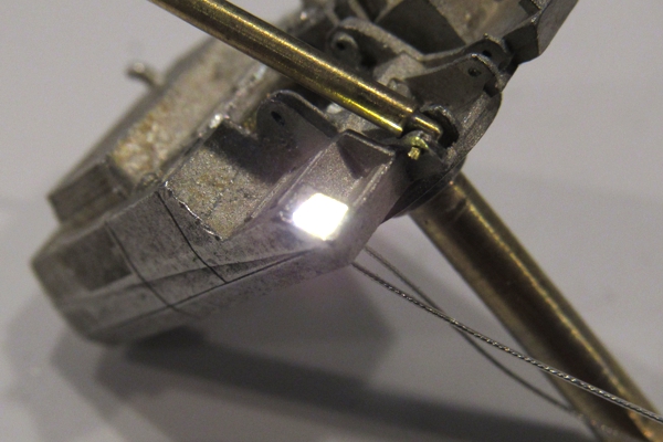
Seeing it light up made it worth the pain of dismantling the thing twice. But I made some additional changes as I reassembled the unit. For one thing, I got tired of cutting and rethreading everything every time I needed to fix something. I decided to connect the threads from the excavator to the threads from the mechanism with wire links. This would not only make it much easier to disassemble, but also make everything adjustable (not unlike what I did for the train order signals)—an even bigger win. It did require relocating the mechanism to accommodate the links; fortunately, the way it's designed, this was just a matter of drilling and tapping two new holes. I also modified the winding drums so I could attach permanent pigtails to which the threads from the excavator would connect. When all is said and done, this is what it looks like:
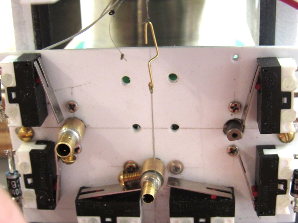
The connecting link passes through eyelets tied to the ends of the threads. The eyelets are made from Scale Hardware 0.5mm washers; the link is 0.015" brass wire. Of course, now that I'm going through all of this trouble, I'll probably never need to dismantle the unit again (I'm sort of counting on it). Sadly, health issues prevented me from catching up to where I was days ago, but at the end of the day, things were looking up. One down, four more to go.
DAY 8. It started out just as most of the other days had: going like gangbusters until I hit a wall. This one was the most vexing I'd faced so far: I got the upper arm working fine, but when I started to work on the bucket, suddenly I found that the bucket's threads were somehow binding inside the tube below the cab. This made less than no sense, since all of the other threads moved freely. But, the only solution was to re-thread the bucket—a task that kept me busy for the next few hours. I did, however, discover the problem along the way: the bucket threads somehow got tangled up with the light wires. At least I didn't have to dismantle everything again.
The day wasn't going to get any better, however. No sooner did I get that problem solved but another one emerged—it was like playing whack-a-mole. Gradually all of the functions began seizing up. Turns out to be a bizarre interaction: the LED wire insulation made the nylon thread sticky (I should have been aware of that after the thread guide failure). I wasn't about to give up the LED, so I replaced the wires, which required removing the cab from the base, and removing the main boom from the cab. There I was deep in the guts once again—I'd removed the main boom from the cab so many times that the holes for the assembly pin was getting worn, and I had to drill it out for the next size up wire. But the worst part was desoldering the wires on an 0402 SMD LED and replacing them with #40 solenoid wire.
Since the start of the project, I was met with more failures than I can count—many more than I've documented here. I removed the cab from the base about 5 times, partially rebuilt the boom assembly twice, rethreaded the whole excavator at least 8 times, and overhauled the mechanism 3 times. Some problems weren't my making; I replaced a faulty control switch, an occasionally uncooperative microswitch, and a geared motor prone to stalling. More than a few times I was ready to throw in the towel. And after a while, I stopped taking photos and videos—it just got to be too much.
Although the bucket action wasn't as smooth as I'd prefer, overall the excavator was fully functional. From here on out, the work was cosmetic.
|
|
DAY 9. As I began the cosmetic work, I discovered why the bucket action wasn't smooth: the thread was getting wrapped around the end of the piston. Thanks to the changes I'd made with the thread connections in the mechanism, it was relatively easy to remove that one thread and relocate the anchor point off-center to avoid the end of the piston. Lo and behold, the bucket was now the smoothest-operating of all the functions. It was on to detailing and painting.
Cosmetic Work
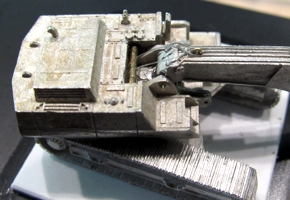
I wasn't going to do it—the model was plenty detailed as it was. But all of those visual compromises required in order to make it functional nagged at me. There was no way to hide or disguise them, so I figured distractions might help, distractions like full hydraulic plumbing (you can tell this was unplanned, because otherwise I'd have removed the cast-on details before construction). This was almost as hard as animating the thing; just finding a material to simulate the hydraulic hoses took several hours. After trying about a half-dozen types of wire, wire insulation and thread, I finally settled on 0.15mm fused nylon beading thread (Beadalon WildFire 161T-008/MZ).
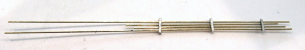
The main hydraulic line harness for the boom (above) comprises four pieces of 0.010" brass wire and three anchor blocks made from pewter scraps drilled out with a #83 drill. For the hose connections, I simply bonded the beading thread to the sides of the ends of the wires. The plumbing alone took a day and a half to complete, but I think it was worth it. The rest of the plumbing was just four little bits of wire, followed by about a dozen bits of hydraulic hose.
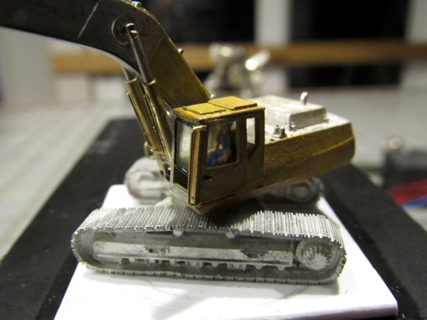
Next, after painting the cab interior (Floquil Depot Buff) and installing a Preiser figure, I glazed and assembled the cab walls. The glazing included the front window which, in real life, is made from two parts; the smaller lower one is left open nearly all of the time. I finished off the front window with a frame made of 0.006" brass wire.
I chose not to use the kit's etched stainless handrails; instead, I made new ones from brass wire. In addition, I disguised part of the brass pin that provides mechanical advantage for the main boom actuating thread by topping it with two bits of styrene L-girder. These also helped keep the hydraulic hoses at the bottom of the boom in check, as they're not connected to anything but the boom.
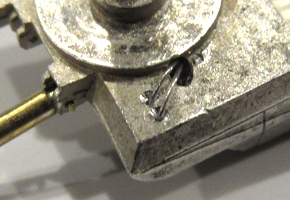
The Part That Almost Killed Me
As such parts go, it was only somewhat complex, although it's mighty small. It's the hydraulic hose harness for the main boom pistons, which comprises four bits of beading thread and three bits of pewter scrap drilled out to accept the thread. It only took about 20 minutes to make; installing it, however, took a gruesome one and a half hours. No exaggeration. And it wasn't even like the spot where it went was hard to reach; it was simply a nightmare getting it into the right position, keeping it there, and hitting it with CA.
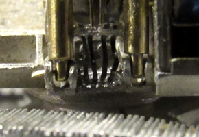
It got so bad at one point I wanted to smash the excavator to smithereens. The problem was that my hands shake, sometimes badly, and everything takes at least ten times longer to do than before. But eventually I did prevail, obviously, although I'm now sporting quite a few more grey hairs than before. And the frustrating irony of it is, you can barely see the bloody little thing (dead center in image above right).
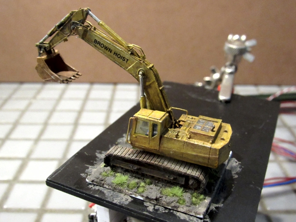
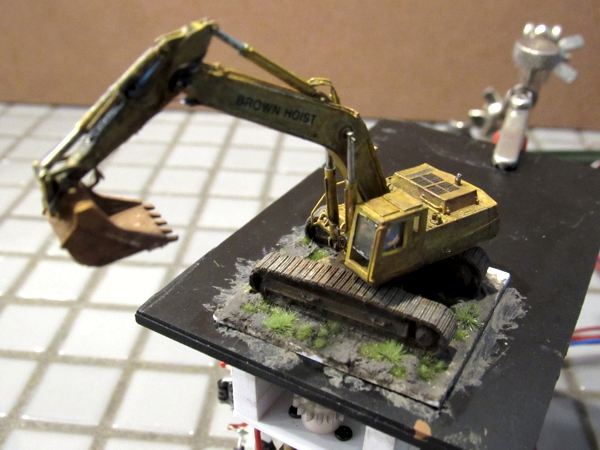
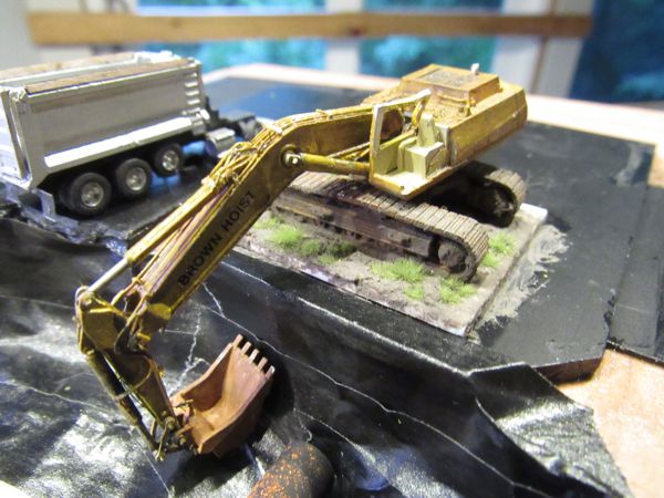
DAY 10. Painting and weathering. Not much to report other than it was exciting to see it all coming together.
|
|
Oh, and yes, I know Brown Hoist doesn't make excavators, but it's what I had on hand that's at least in the same general genre of equipment. I may replace it with Komatsu someday if I'm ambitious.
Tragedy
On 2 July 2022, tragedy struck. I dropped the Men at Work diorama on a tiled counter; naturally it landed "butter side down." The excavator took the brunt of the damage: the excavator body was separated from drive below; the boom raise/lower thread snapped;there was some cosmetic damage to the boom; and the cab was completely demolished. Repairs began the following day.
Regrettably, I was not able to correct all of the mechanical damage: some of the pivots became permanently bent, throwing the entire boom off kilter, and some of the functions are now erratic. But it all still works, which I wasn't expecting; I feared it had been totally trashed.
Minor Upgrade
On 24 August 2022 I finally figured out how to add a control for the light to the controller box. The problem: the LED needed 3 VDC, whereas all of the motors ran on 1.5 VDC. In order to add a control for the light, I'd need two more wires, but the cable connector only had one spare. So I put on my thinking cap and devised a way to use one of the motor batteries and add another to get the 3VDC I needed, while still using the common return, which meant I only needed one more wire. It was quite the challenge squeezing another battery into an already packed controller box, but eventually I succeeded. This eliminated the awkward arrangement I originally devised that had the light control on the main diorama control panel, separate from the excavator controller. Yay.