Crossing Gates
Version 1
Although this is perhaps one of the more obvious things to animate, I was convinced I could remove it from the realm of toys by "doing it right." Basically this just meant running the gates very slowly. Based on the voluminous responses I've received, it worked.
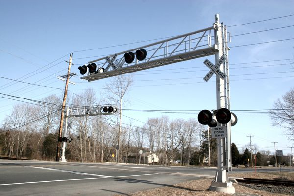
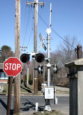
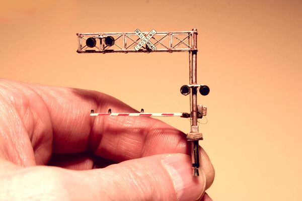
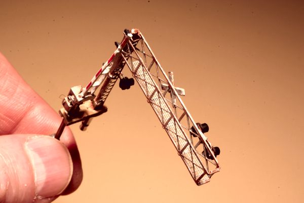
The gates themselves date from my White River & Northern IV, circa 1998. Back then I used a Tortoise switch machine to animate them. The flashers were scratchbuilt with LEDs wired to a mini-phono plug, so that the entire assembly could be removed from the layout for maintenance or to keep them safe while working on the layout. The gate arms were also fitted with SMD LEDs, so all of the lights worked. They were switched on and off via the electrical contacts on the Tortoise, and powered via ultra-fine solenoid wire. The overhead signal gantry was scratchbuilt using etched brass bridge parts and a bit of stainless steel roofwalk. It was not modeled after a particular prototype; it was instead generic.
Version 2a
I reinstalled them on 15 April 2020. Just as on the WR&N IV, they plug into mini-phono jacks mounted on the layout.
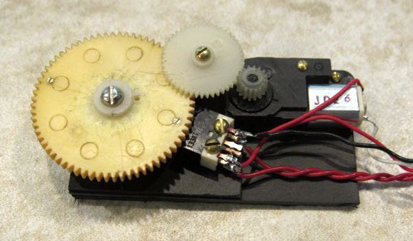
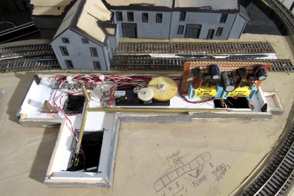
Making them function was quite the challenge, due to the fact that I was very limited as to what I could do mechanism-wise because there was only a one-inch space between the base and the layout surface. I wound up installing the mechanism inside a factory. I actually built it twice. The first one was a large, complex linear drive:
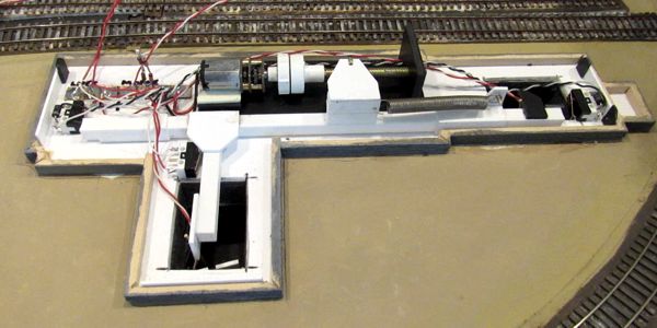
This video turned into one of my most popular, with tens of thousands of views:
|
|
Version 2b
On 28 May 2020 I tore out the linear drive to make room for the turbine vents. Also, the old drive was quite noisy. The new rotary drive (below) was far smaller and much quieter than the original.
|
|
Version 3
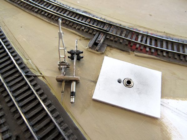
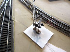
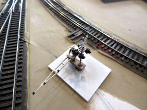
The gates are now installed on the Men at Work diorama: it's still the same gates I made in 1998, just yet another whole new mechanism (the fourth). Owing to their all-new flashers, they could no longer be "unplugged" from the layout. But that turned out to be okay, since the small diorama doesn't have to endure the same construction and maintenance rigors of a layout. Also, because there was a generous amount of space beneath the surface, I could create a new drive with no constraints. Ultimately, I took a cue from the other animations I've done so far: I permanently mounted both gates to a single base plate, which allowed me to be much more precise with the mechanism.
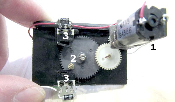
The new mechanism takes a rather different approach than I've used up to now: I wanted the behavior of a linear drive, but with the simplicity of a crank. The motor (1) drives a large pinion (2) that only rotates a portion of a full circle; the short arc traced by the crank is nearly linear, versus the sine wave traced by a crank's full rotation over time. Thus, the gates would move at a constant velocity from start to finish. Limit switches (3) control how far the crank is allowed to move.
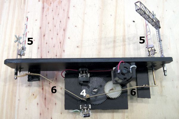
Motion is transferred from the crank pin (4) to the gates (5) via two long levers (6); the crank pin engages the levers as well as the limit switches. Despite appearances, the geometry of the two levers (length, pivot location) is the same, so the gates move in perfect sync; the levers are also easily bent to adjust their range of motion. Being brass castings, the gates have enough weight to drop to the down position via gravity; their actuator wires simply rest on the ends of the levers.
|
|
Lights
Installation of the 20 flashing LEDs on these signals is covered separately.
|
|
Reference