
Fireworks
As an admirer of Rick Spano's famous fireworks display, I've wanted to make one of my own. However, it's more than likely I'll never live to see the day. I've made many attempts using a wide variety of techniques, but nothing has ever come to fruition. Here, for the curious, are some of my experiments...
I've attended dozens of fireworks shows in small-town New Hampshire back in the day, and they were all the same: truly pitiful by today's standards. But back then, small towns had small budgets, and families nevertheless had a terrific time gathering in the town's high school sports field for some hot dogs and a little light show. The people watching from their cars would show their appreciation for each individual rocket—launched a minute or more apart—by flashing their headlights. The grand finale was usually just five or six rockets set off at once and, on occasion, some ground displays. I miss those simpler times; now, as if it was an arms race, everyone is trying to out-do one another, with multi-million-dollar shows having synchronized music and lasers and who knows what all else. I used to love fireworks shows, but I haven't been to one in well over a decade.
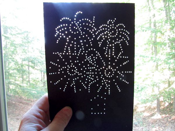
One day I got it in my head to make a fireworks display with LEDs and the same electronics I'd used for the fireflies. So I built a test unit, and it was... okay. It wasn't spectacular, but seemed as though it might be worth taking further. One change I made right away was to switch from pre-wired 0402 SMD LEDs to 1.6mm discrete LEDs: they were easier to work with, and I had more of them; however, it meant cutting two wires and making four solder connections for each LED.
|
|
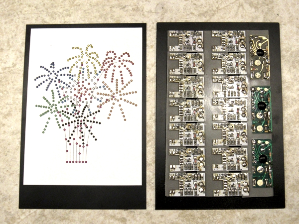
I had enough parts to make five displays, which was about half as many as I'd originally wanted. But that turned out to be a good thing, because the assembly statistics for five were still staggering. Each display consists of twelve banks of seven LEDs, or 84 LEDs, plus the "launch" pattern, which is 9 more LEDs, for a total of 93 LEDs per display. Five displays required 465 LEDs, plus 10 more for a "sparkle" effect (using the same electronics as the wedding photographers); this translated to a total of 555 wires or 1,110 solder connections, not including 280 power supply connections. Work began on 6 October 2020 with the chip extraction process, which took a day and a half. Then I created a color-coded drawing of the five displays, which greatly helped me interleave the LEDs for a more compact assembly. I printed the drawing on self-adhesive label stock and applied it to a piece of 0.030" black sheet styrene.
Next, I made a circuit board mounting plate from ⅛-inch thick sheet styrene the same size as the display sheet, and attached all 70 flasher chips with double-sided foam tape (above left). Just wiring the power leads (above right) took half a day. To keep the hundreds of LED wires relatively neat, I also drilled holes through the chip plate, one for each chip; the chips would face outward to facilitate making the final connections (below left). To the back of the chip plate I attached strip styrene spacers around the edges so the two layers could be sandwiched together (below right) once the LEDs were all wired.
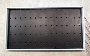
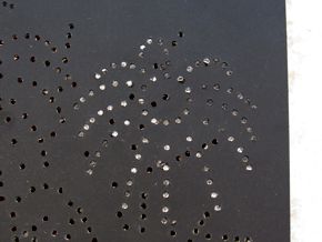
Then came the excruciatingly tedious task of installing and wiring the LEDs, which began with 475 hand-drilled holes (below).
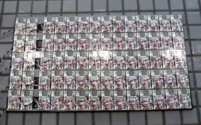
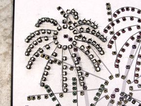
Each LED was bonded into a hole with CA (below left); afterward, the LED anode leads were bent and soldered together (below right) to form twelve pre-wired "sprays" for four of the five displays; the fifth display was too large to use this trick, and so I used brass rod to connect the LED anodes. It was painfully slow-going; the displays took nearly a day each to install. The "sparkle" effect for one of the displays utilizes the same electronics as the wedding photographers.
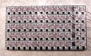
But if I thought that was slow-going, I was about to embark on an even slower process: cutting, soldering and bundling 555 pieces of wire. I could only do a few bundles at a time before I'd go a little nuts, so this became an ongoing process; each display took on average two days to wire. By 29 October 2020 I'd finally finished attaching all 555 wires to the LEDs (below).
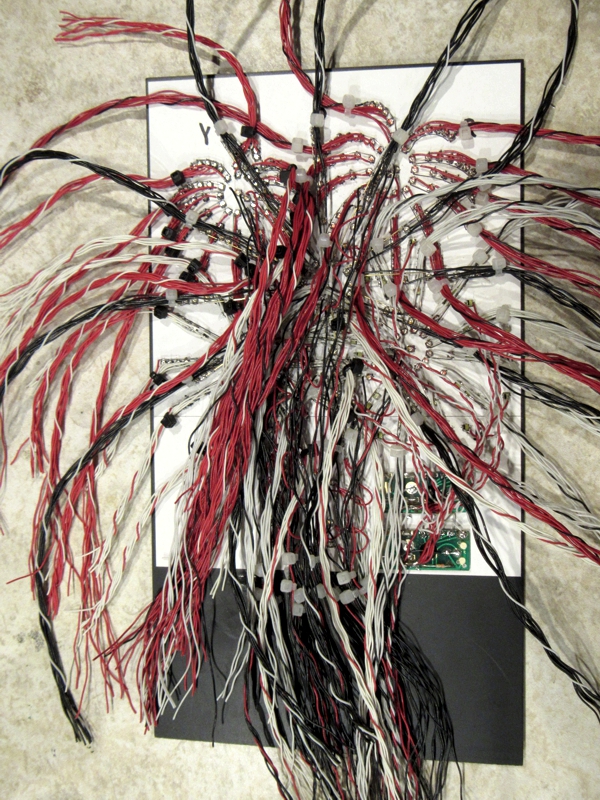
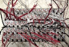
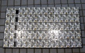
This was followed by threading all of the wire bundles through the chip panel (above left and right), then cutting the wires and soldering them to the chips. Oh, and before making the final connections, I had to test each wire to determine which of seven LEDs it powered. Tedium doesn't begin to describe the process. But, I never completed this step due to...
Problems
My modeling mentor Rick Spano once said, when you're building something unique, you really need to build it twice, so the second time you can fix all of the goofs you made the first time. The fireworks display is a perfect example: I made some serious mistakes that could not be corrected.
TOO MUCH SYMMETRY. The displays looked more artificial than they ought to, because I designed them around perfectly symmetrical patterns. I should have randomized the lengths and angles of the sprays.
LIGHT BLEED-THROUGH. As I began testing the more compact and brighter displays, I started seeing an objectionable amount of light bleeding from illuminated LEDs into neighboring non-illuminated ones for different displays, which I hadn't anticipated. The look was definitely less than ideal.
NEEDLESSLY COMPLEX. Each spray of LEDs for each display had its own chip. I did this because I determined the chips could drive at most 3-4 1.6mm LEDs. I could have built driver boards so that a single chip could handle all of the LEDs in a display; or, I could have used different LEDs and/or cut back on the number of sprays.
LOSS OF SYNCHRONIZATION. Because each display had 12 chips, I couldn't leave them running continuously on their own because each chip ran at a slightly different rate; consequently, the display became a jumbled mess after just a few seconds (which worked to my advantage for the fireflies). In order to re-sync all of the chips, I'd need to do a power cycle, which would have made programming much more complex.
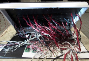
NOT ENOUGH WIRE. I should have doubled the length of the wires to allow the front and back parts to separate for troubleshooting. It would have required the unit to be twice as thick.
TOO MANY FAILURES. Once I started soldering the wire bundles, I'd more or less painted myself into a corner, and could not make repairs to LEDs or wiring that failed. After finding about a half-dozen dead LEDs, I was still willing to carry on; however, when I discovered a couple of entire sprays that were dead, I realized it was time to end this futile exercise.
BIG AND HEAVY. At 6" x 11", the unit would have required a larger hill than I'd preferred in order to hide it. It was also quite heavy, necessitating a more powerful motor to raise it up into operating position.
Version 2.0
I'd arrived at a crossroads: try for Version 2.0, or abandon ship. It was a tough call, since I'd invested hundreds of LEDs, many feet of wire and weeks of time in something that would get tossed. I don't like quitting, and I felt I'd learned enough to tackle a new version with more confidence, so I began by doing some quick tests. I'd burned through most of my 1.6mm discrete LEDs, so I switched back to prewired 0402 SMDs. How many of them could I drive on a single channel of a single chip? Turns out to be 8-9 LEDs, which would create a fairly acceptable display, so I ran a chip for a while to ensure I wasn't overloading it. The new displays would be dimmer, but to be honest, the 1.6mm LEDs were just a bit too bright—I was planning on sanding their faces to diffuse the light a little. Plus, using single chips meant the displays would never get out of sync.
Each display went from 12 banks of 7 LEDs driven by 12 chips down to 9 banks of 6 LEDs driven by only one chip (plus a single cool white LED for the initial "burst"). Also, the "launch" simulation went from 10 LEDs and 2 chips down to 7 LEDs and one chip for each display. I would, however, need to recycle chips from the first unit, as I'd used up all of the 7-channel ones.
Switching back to 0402s meant I could make the unit nearly one-third the size. I could also more tightly integrate the displays, and as an even bigger bonus—because I was using fewer LEDs and far fewer chips per display—I could have more displays, which I'd wanted anyway. Now I'd have 7 instead of 5: red, orange, yellow, green, blue, white, and as the pièce de résistance, a great big red, white and blue number with lots of sparkles.
Drawing from lessons learned, I began by planning the LED arrangement on my computer, as before, except this time I free-handed the displays so they'd be more randomized and natural-looking (below left). Also as before, the LEDs would be mounted on a piece of 0.020" black sheet styrene, except this time the SMDs would be press-fit into holes such that they'd be completely embedded in the styrene, thus preventing light bleed. I tested all of this before getting to work on the actual unit. The chips were mounted to a ⅛-inch thick sheet styrene panel, as before (below right), except this time the wires will remain internal, instead of passing through holes to external connections.
Based on prior experience, the non-zero failure rate of the LEDs and the chips meant that I was faced with an arduous task involving the following steps, all of which had to be done for each individual LED one at a time (as opposed to batches of them, as before):
- test LED
- drill hole
- press-fit LED into hole
- secure LED with CA
- wait for CA to cure if the fit is loose
Also, as before, I could only do so many at a time before I'd go a little nutty. Plus, there were failures; I was thankful for making the design changes I did so I could make repairs.
Programming
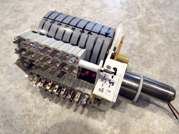
I like mechanical stuff; that's why the neon open sign in the laundromat has a motorized drum with wiper contacts. For the fireworks, I'd need something a bit more robust, and for that I turned to the stoplight control unit from the White River & Northern IV, which I'd built back on 3 February 1998 (I used to date everything I built in those days) and wisely kept. It works something like a player piano: raised ribs on a motorized drum actuate roller microswitches to control the stoplights for a five-way intersection—complete with left-turn signals and walk/don't walk signs.
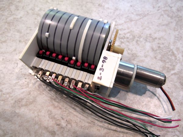
I've figured out a way to repurpose the mechanism, which saved me considerable time and effort: since the launch and display LEDs are always in lockstep with each other, they didn't need their own separate "channels" on the drum; I simply mounted the additional microswitches right above the existing ones (below). Thus the WR&N IV will live on—after a fashion. The work was completed on 5 November 2020, and duly recorded on the device.
And this is where the story ends. The player piano was re-re-programmed for a new set of stoplights on the Men at Work diorama, while all of the LEDs, chips, wires and whatnot were either scavenged for other projects, or tossed out. Perhaps if I live long enough I'll get something to work, but such a hope is dimming quickly.