
Train Order Signals
The advantage I had in modeling operating train order signals is that they were usually operated manually, which meant I didn't need to try and obfuscate the actuating rods; indeed, they needed to be seen. One other advantage I had in my particular situation is that the front of the station faced the back of the layout, so I didn't need to simulate the bell cranks and rods running into the station; I could allow the rods to drop simply through the ground.
The first step was to gather all of the materials:
- two Showcase Miniatures semaphore signal kits
- etched brass washers left over from a cart kit
- 0.0325" brass tubing
- 0.0625" square brass tubing
- 0.010" brass wire
- two miniature straight pins
- two 0603 warm white SMD LEDs
- two micro-gearhead motors
- two sub-miniature lever microswitches
- various toy gears, screws, washers, and other spare parts
- bits of strip and sheet styrene, double-sided foam tape, etc.
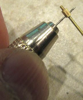
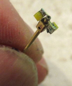
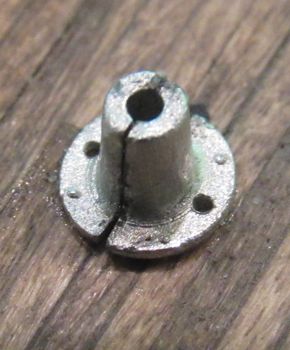
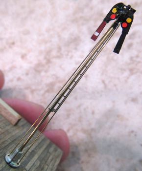
Construction was something akin to a chess match: one had to plan several moves ahead before executing any one step in order to prevent painting oneself into a corner. First, I cut an 0.010" long bit of 0.0625" square brass tubing, and soldered it near the end of some 0.0325" brass tubing (below left). Then I drilled a hole, sized to make a gentle press-fit with the miniature straight pins, through the lower end of the square tubing (below right).
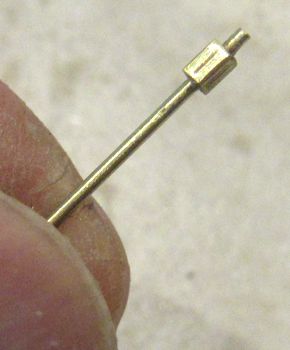
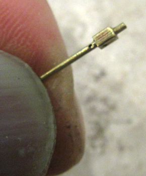
Next, I drilled a #83 hole below the square tubing through one side of the round tubing (below left), then another #83 hole diagonally across near the top of the square tubing (below right), into which I soldered a bit of 0.010" brass wire rod.
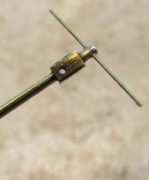
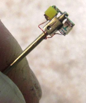
I soldered the tops of the two SMD LEDs to the wire at the top of the pole (below left), then attached #40 solenoid wire to the bottoms of the LEDs, and threaded the wires through the lower #83 hole (below right), testing the LEDs at each step.
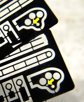
In the semaphore heads, I drilled #83 holes at the lower side of the pivot (yellow arrows, below left), assembled and painted the blades, then filled in the roundels with Tamiya transparent paint (below right), allowing it to dry a minimum of an hour.
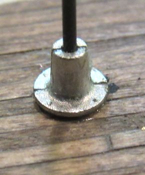
I assembled the stanchion base on the station platform, using a #67 drill bit as a stand-in for the stanchion (below left), so I could then drill a pair of #73 holes through the base for the actuating rods (below right).
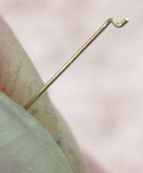
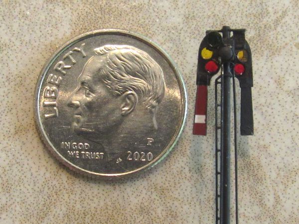
After painting the entire signal head black and cleaning off the faces of the LEDs, it was time to assemble the signals. First, I attached the blades to the mast head with clipped-off miniature pins, placing etched brass washers behind the blades (below left). This was the scariest part of the entire project: even though it was a "gentle" press-fit, the forces required to set the pins was still enough to completely demolish the entire signal head if I slipped. Then I made the actuating rods by bending tiny Z offsets in the ends of 0.010" brass wire to engage the blades (below right), and inserted the rods into the holes in the blades.
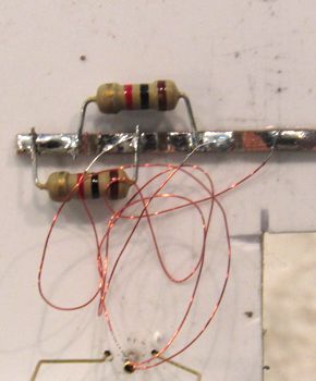
After carefully adding the ladder, I quickly mounted the signal in the base where it would be safe from any further handling (below left); then I connected the LED wires to a small terminal strip with appropriate load resistors (below right).
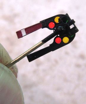
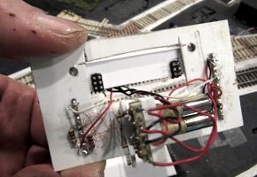
I was finally ready to start fabricating the drive system. I'd built three of these, each one taking a day to make. The first two proved to be inadequate: too fast, prone to jamming, difficult to control, etc., etc. The third isn't perfect, but it gets the job done (below).
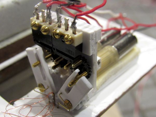
It consists of two micro-gearhead motors that engage index gears fitted with four index pins. These pins trip sub-miniature microswitches to stop the motors at appropriate points for the signal aspects. A pair of actuator levers translate the rotary motion of the longer index pins into vertical movement to move the signal blades. The actuator wires that move the blades have V-bends at the levers to allow fine adjustment.
Since videos are worth far more than thousands of words, here are three I produced showing how the signals work.
|
|
|
|
|
|
Postscript: I've since moved the layout's temporal setting up several years, and it's quite possible the signals were no longer in use by 1959. No matter; the exercise was more than worth it.
To Keep Them or Not
I was on the fence about the working train order signals: they have no right being on a little branchline. Eventually, however, I caved in and kept them: I'd poured my heart and soul into the effect, and decided to invoke Rule #1 (it's my railroad) so that I might enjoy them. They were installed on the morning of 17 May 2021.

I was uncomfortable permanently installing the station base: this would prevent me from performing any maintenance on the train order signal mechanism. When I came across some modular micro-connectors on 6 June 2021, I devised a plug arrangement for the station base. Below left are the sockets attached to a plate glued to the layout base; below right are the corresponding plugs, just left and right of center. One plug/socket carries the signal control circuits; the other is for lighting.
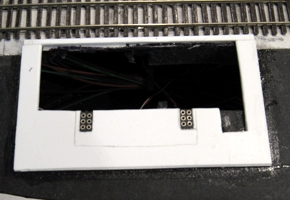
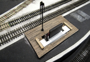
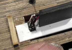
Above left is a detail shot of the plug wiring for the signals; above right is the base plugged into the layout. The rectangle of black styrene sticking up in the middle is a handle to pull the base off of the layout—it takes a fair bit of effort to disengage it.
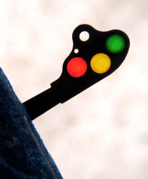
The signal now appears on the Yesteryear diorama.