
Lighting Fundamentals: LED Basics
LEDs, or Light Emitting Diodes, are solid state devices that produce light with virtually no heat. They produce a wide range of colors, including different shades of white, and last far longer than incandescent lamps. They have seen increasing use in modeling, to the point that incandescent lamps are virtually non-existent in the hobby today.
LEDs produce light through a process of moving electrons around within a semiconductor (to put it in extremely broad, only somewhat correct terms), whereas incandescent lamps produce light by heating a piece of tungsten wire until it glows white-hot. This is why they get hot; indeed, in terms of energy used, they produce far more heat than light.
The Most Important Rule
Under most circumstances, given the proper rating, incandescent lamps can be operated directly, with no other components required. By contrast, because an LED does not consume energy the same way, it requires a resistor to prevent damage or destruction. Thus, the most important rule is:
Never operate an LED without a resistor.
LEDs and Polarity
It's important to note that LEDs are polarity-sensitive; that is, they operate only one way in a circuit. This can be used to your advantage: for instance, it makes directional headlights a snap. But it can also fool you into thinking that an LED is bad. Thus, rule number two is: An LED cathode (negative lead) must be connected to the negative terminal of a power supply in order to work.
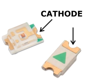
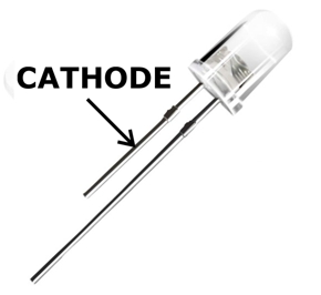
Is there a way to identify their polarity without testing them? Yes. You can identify the cathode several different ways:
- the cathode lead is shorter
- the cathode is marked with ink or dye
- a notch on the base of the LED is beside the cathode
- an arrow printed on the LED points to the cathode
- if prewired, the black wire is the cathode
- if prewired with the same color wires, the shorter wire is the cathode
Here is the electrical symbol used for an LED, with the cathode identified:
Just remember that the arrow points to the negative terminal of a DC power supply.
Can LEDs work on AC? Yes, they can. However, they won't be as bright since they'll only be lit half the time, and they may have a perceptible flicker. Also, it's recommended to include a regular diode (such as a 1N4001) wired in reverse, parallel to the LED, to prevent damage from excessive reverse polarity current.
Rare Exceptions
There are a few LEDs that have load resistors built-in, thus eliminating the need for external resistors. These LEDs are quite rare, however, and are not as handy as they may sound: since the resistor is built-in, there's no changing it should you have a voltage supply different from what's recommended.
As it is, many LEDs sold for the hobby market—in particular, pre-wired LEDs—may have resistors already wired to the LED. These are relatively easy to spot, since they're external to the LED, and are almost always wrapped in shrink-wrap. 90% of the time the resistors are 1K, which is a pretty typical all-purpose value. But you may still want to run tests to see if they produce the desired brightness (see "Scale Brightness," below).
Series vs. Parallel
You can either operate multiple LEDs with individual resistors, or run the LEDs in series or parallel. What's the difference? Series is when the LEDs are daisy-chained together:
Parallel means all of the LED leads are connected together:
The two arrangements have different wiring and power requirements, and will involve different resistor values. Series requires a higher supply voltage, since all of the LED voltage requirements are added together. Parallel requires lower voltage, but more current, since all of the LED current requirements are added together. I prefer using individual resistors whenever practical; individual resistors solves the problem of different requirements when using different color and/or type LEDs together. It also solves problems that arise when (in the rare instance) an LED should fail.
Resistor Values
It bears repeating:
Never operate an LED without a resistor.
The value of the resistor required is a function of the power supply rating versus the LED operating specification. There are countless resources online to help you determine the proper resistor to use. However, when operated at full spec, most modern LEDs are too bright for modeling applications, so strictly following guidelines doesn't always produce the desired results (more on this topic later). Also, in some cases you might have two or more LEDs connected in series, which changes the resistor needed.
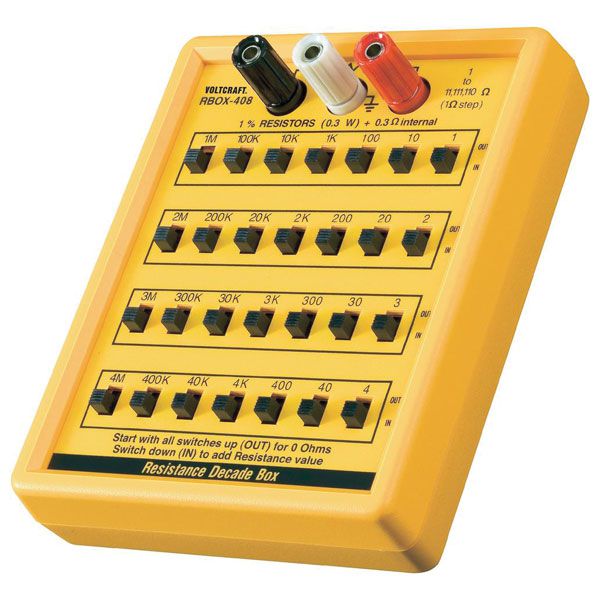
What's the alternative? A good idea is to get a "decade box" (a device containing an array of resistors) to determine the resistor value you need. When using a decade box, always start with the highest resistor value and work your way down until you reach the desired brightness.
This all sounds like a lot of work. Is there a shortcut? Yes. When in doubt, start with a 1k (1,000) ohm resistor. It will work for most power supply voltages, from 6 to 12, typically. If the LED is too dim, try a 470 ohm resistor. It's rare you'd need to go much lower.
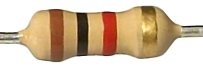
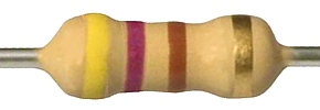
How do you identify resistors? They have colored stripes, and the color pattern indicates the value. Again, there are tons of resources online to help you. But since there are just a couple of values you need to be familiar with, at least for starters, here's what to look for:
 |
 |
1k ohm |
470 ohm |
Quarter-watt resistors are perfectly adequate for LED applications.
Colors, Sizes and Packages
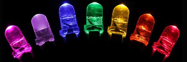
Once upon a time there were only red LEDs. Then came green ones. Then there was a long wait until blue ones were finally developed; not only did blue LEDs make full-color LED displays possible, but they also gave rise to the now-ubiquitous white LEDs. In addition, a great many colors are now available, including pink, lavender, yellow-green, aqua blue, orange, ultraviolet, infrared, and many others. Packages may be water clear, tinted, diffuse, etc. Note that LEDs of different colors may have different electrical characteristics.
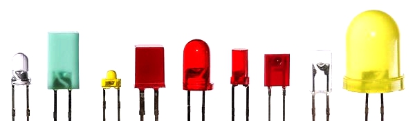
LEDs come in a staggering array of sizes, shapes, packaging styles, etc. The two most common packages that modelers will encounter are DIP and SMD.
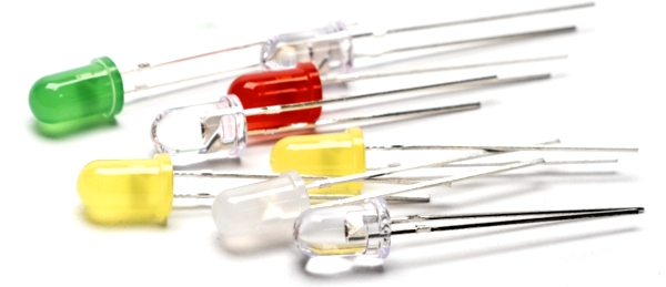
DIP (Dual Inline Package). This is a familiar, traditional package having a round body and a pair of parallel leads. Sizes are designated in millimeters at the lens; common sizes include 5mm, 3mm and 1.8mm. Shapes include dome, hat-top, inverted, and others.
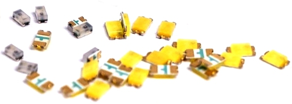
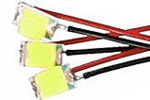 SMD (Surface Mount Device). These are designated by their
overall package size in thousandths of an inch, abbreviated as a four digit code. Since they're intended for automated assembly, they can be difficult to work with;
however, most sizes are available pre-wired (right). Here are just a few sizes commonly found in modeling:
SMD (Surface Mount Device). These are designated by their
overall package size in thousandths of an inch, abbreviated as a four digit code. Since they're intended for automated assembly, they can be difficult to work with;
however, most sizes are available pre-wired (right). Here are just a few sizes commonly found in modeling:
Package Code |
Size in Inches |
Size in mm |
1206 |
0.126" x 0.063" |
3.2 mm x 1.6 mm |
0805 |
0.080" x 0.050" |
2.0 mm x 1.25 mm |
0603 |
0.063" x 0.032" |
1.6 mm x 0.8 mm |
0402 |
0.040" x 0.020" |
1.0 mm x 0.5 mm |
0201 |
0.024" x 0.012" |
0.6 mm x 0.3 mm |
I'm barely scratching the surface here, just to give the uninitiated a taste. There are loads of online resources to help you learn much more. Just be cautious: it's a bottomless rabbit hole that can be overwhelming, especially considering the technology continues growing at a dizzying pace.
Testing and Evaluating
I built the ultimate LED tester/evaluator; it's been one of my most useful tools. It takes the guesswork out of the process of what voltage/resistor combination works best. A commercial "decade box" (below) will also work if you prefer not building such a tool; in this case you'll need a DC supply, and batteries will work fine.
Scale Brightness
One of the biggest mistakes modelers make when using LEDs is not controlling their brightness. Many LEDs today are far brighter than they used to be when they were first introduced and, more particularly, much brighter than they need to be in most modeling applications. This is especially true of LEDs that are directly visible—for example, signals and streetlights, as opposed to building interior illumination. This is what I refer to as "scale brightness," that is, the brightness one perceives as being correct for the scale size of a light. LEDs that are too bright tend to ruin realism. Therefore, it becomes very important to control their brightness. If anything, err on the dimmer side to be safe, especially in areas where there is a lot of illumination, such as a busy urban street.
This is not difficult to do. If the LEDs have a recommended resistor value, start by doubling it. If the resistor value is not known, then good old fashioned trial and error will work just fine. Start with a 1k resistor, then double it, triple it, etcetera. Build or buy a resistor "decade box" (above) to make the process easier. Also be sure to run a test with the LEDs in their finished form and at or near their final location on the layout so you can be sure the brightness is appropriate. I think you'll be surprised how less can be more.